American National Standard
Recommended Erection Instructions for Steel Frames
ANSI/SDI A250.11-2022
View PDF
Table of Contents
- Scope
- Storage and Premliminary Assembly
- Plumbing and Bracing Frames
- Accessories
- New Masonry Construction
- Existing Masonry Construction
- Steel Stud Wall Construction, Studs Erected with Frame
- Double Egress Frames in Steel Stud Wall Construction
- Wood Stud Construction, Studs Erected with Frame
- Wood/Steel Stud Construction, Studs Erected before Frame
- Slip-on Drywall
- Butted or Existing Steel or Wood Stud Wall Construction
Annexes
A. Manufacturing Tolerances for Standard Steel Doors and Frames
1. Scope
1.1 Recommended methods for the installation of steel frames for swinging doors in a variety of wall conditions, commonly used in commercial buildings, are covered within this standard. The installation of transom/sidelight (or panel) type frames and single or multiple borrowed lights are not covered in this standard.
1.1.1 It is not the intention of this document to obstruct the development of alternative installation methods, nor is it intended to restrict frame installation solely to the wall types noted herein.
1.1.2 Although this document is commonly referenced for severe windstorm installations, critical performance requirements (such as type, quantity, and location of anchors) shall be as indicated in the manufacturer’s published Approvals or Listings.
1.2 Reference documents
- SDI 127E – Prime Painted Materials Alert
- SDI 127F – Butted Frames Rough Opening Sizes
- SDI 127J – Back-Coating of Frames
- SDI 117 – Manufacturing Tolerances for Standard Steel Doors and Frames
- NFPA 80 – Standard for Fire Doors and Other Opening Protectives
- UL10C – Standard for Safety Positive Pressure Fire Tests of Door Assemblies
- ANSI/SDI A250.8 – Recommended Specifications for Standard Doors and Frames
- HMMA 840-16 – Installation and Storage of Hollow Metal Doors and Frames
- HMMA 841-13 – Tolerances and Clearances for Commercial Hollow Metal Doors and Frames
1.2.1 Further information on wall construction, anchoring, details, manufacturing tolerances or installation may be found in the following:
- SDI 110 – Standard Steel Doors and Frames for Modular Masonry Construction
- SDI 111-A-H – Recommended Standard Details for Steel Doors, Frames, Accessories and Related Components
- SDI 122 – Installation and Troubleshooting Guide for Standard Steel Doors and Frames
- SDI 127D – Electric Strikes in Stud Walls
1.3 Metrication
1.3.1 Standard dimensions used in this document are in inch-pound units. Metric values, where applicable, are included in parenthesis for reference only. These are “soft conversion” approximates.
Values stated without parentheses are the requirement. Values in parentheses are explanatory or approximate information.
1.4 Notes
1.4.1 Tolerances
Note: All values which do not carry specific tolerances or are not marked maximum or minimum shall have the following tolerances: Linear dimensions shall be ± 1/16 in. (1.6 mm). Weight or force shall be ± 2%. Angles shall be ± 2 degrees. Where only minus tolerances are given, the dimensions are permitted to be exceeded at the option of the manufacturers.
1.4.2 Gauge vs. Thickness
While the term ‘gauge’ is no longer common for defining material thickness it is still used to specify doors and frames for ordering purposes. The term ‘thickness’ is used when defining the actual dimension of an item, and the term ‘gauge’ is used in the context of specifying a particular door or frame.
1.4.3 Frame Installation in Cast-In-Place Concrete Walls
While the use of hollow metal frames in cast-in-place concrete walls is a common construction practice, the SDI does not recommend the inclusion of the frame as part of the process of pouring the wall. Instead, a rough-opening should be blocked out no less than 3/16″ (4.8 mm) larger than the frame on all three sides. For example the opening for a 3′ 0″ x 7′ 0″ standard frame with 2″ faces would be 3′ 4-3/8″ x 7′ 2-3/16″ minimum. The installer is responsible for anchoring the frame per the manufacturer’s installation instructions, shimming and aligning as necessary.
2. Storage and preliminary assembly (see SDI 127E, and ANSI/SDI A250.8)
2.1 All frames, including knocked-down, shall be stored under cover.
2.1.1 Knocked-down frames shall be placed flat on at least 4˝ (102 mm) wood sills to prevent the frames from resting on the ground.
2.1.2 Assembled frames shall be stored vertically. The units shall be placed on at least 4˝ (102 mm) high wood sills or in a manner that will prevent rust or damage.
2.1.3 The use of non-vented plastic or canvas shelters that can create a humidity chamber shall be avoided.
2.1.4 Refer to project specifications for required cleanup and touchup work.
2.2 Back Coating
(see SDI 127J for further information)
2.2.1 When temperature conditions necessitate the use of anti-freezing agents in plaster or mortar, the inside of the frame shall be coated at the jobsite with a corrosion resistant coating by the contractor responsible for installation.
2.3 Grouting of frames
(see ANSI/SDI A250.8 for further information)
2.3.1 Where grouting is required in masonry installations, frames shall be braced or fastened in such a way that will prevent the pressure of the grout from deforming the frame members.
2.3.2 Grout shall be mixed to provide a 4˝ (102 mm) maximum slump consistency (self-consolidating grout), and be hand troweled into place. Grout mixed to a thinner “pumpable” consistency shall not be used.
2.3.3 Standard mortar protection in frames is not intended for thin consistency grout. Steel frames, including fire rated frames, do not require grouting. Grouting is not recommended for frames installed in drywall.
2.4 Assembly of frame/anchor provisions
2.4.1 Follow manufacturers’ recommended procedure for assembly of frame and quantity and spacing of anchors. If not indicated, install anchors at hinge levels and directly opposite at strike jamb.
2.5 Verification
2.5.1 Prior to installation, jobsite personnel shall ensure correct swing, size and labeling.
2.6 Installation tolerances
2.6.1 Openings will not function properly if the frame is not installed within recognized tolerances.
Figure 1 shows examples of the accuracy to be maintained while setting frames.

3. Plumbing and bracing frames
3.1 Wood Spreaders (see Figure 2)
The Contractor(s) responsible for installation shall have available a sufficient supply of wood spreaders for bracing frames. Spreader bars for shipping purposes shall not be used as installation spreaders.
3.1.1 Wood spreaders shall be square and fabricated from lumber no less than 1˝ (25.4 mm) thick. Correct length is the door opening width between the jambs at the header (i.e., Single Door 3´-0˝ = 36˝= 915 mm). Length tolerance is +1/16˝, -0˝ (+1.6 mm, –0). Cut clearance notches for frame stops. Spreader shall be nearly as wide as frame jamb depth for proper installation.

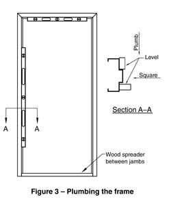
3.2 Equipment for plumbing the frame (see Figure 3)
3.2.1 The contractor should be equipped with a carpenter level, square and wood spreaders.
3.2.2 Where welded frames are provided with spreader bars, they shall be removed with a suitable saw or chisel and filed flush before setting frames. Any bare metal surfaces shall be retouched with suitable primer.
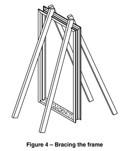
3.3 Bracing the frame (see Figure 4)
3.3.1 Frame bracing shall be as shown or shore to a structure above.
3.3.2 Bracing shall be perpendicular to the intended wall.
3.4 Positioning the frame
3.4.1 Set the frame in the desired location and level the header. Square jambs to header. Shim under jambs if necessary. With frame properly aligned, insert wood spreaders at bottom and mid-height and fasten jambs to floor through floor anchors.
3.4.2 Plumb and square jambs. Install vertical brace to support header for openings over 4´-0˝ (1219 mm) wide.
3.4.3 Do not remove spreaders until wall is erected and cured.
4. Accessories
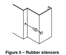
4.1 Install rubber silencers (see Figure 5)
4.1.1 Install rubber silencers before frame erection to avoid grout filling rubber silencer holes. In some cases rubber silencers are factory installed.
4.1.2 Cut the point from a #6d box or finishing nail. Insert nail in hole to elongate rubber silencers.
Moisten the end and insert rubber silencers in predrilled holes on frame stop, remove nail. The thickness of the silencer shall permit latching of door with 1/16˝ to 3/32˝ (1.6 to 2.4 mm) clearance between face of door and stop of frame.
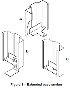
4.2 Extended base anchor (see Figure 6)
4.2.1 Extended base anchors are supplied upon request only. (If required for tool attachment.)
5. New masonry construction (see Figure 7)
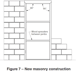
5.1 Assemble frame per manufacturer’s instructions.
5.2 Erect, brace, square and plumb frame.
5.2.1 Fasten frame to floor through base anchors.
5.3 Set second spreader at the mid-height of the door opening to maintain the door opening size. See Annex B for proper spacing of spreaders.
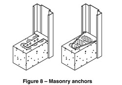
5.4 Install anchors (see Figure 8). Utilize mortar in the area of all anchors ensuring each anchor is embedded into the masonry joint. When grouting of frames is specified or required, adhere to the project specifications listed therein (See SDI’s The Risks of Grouting Steel Frames).
5.4.1 Frames may also be supplied with anchors welded in place.
5.5 Continually check plumb and square as wall progresses.
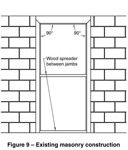
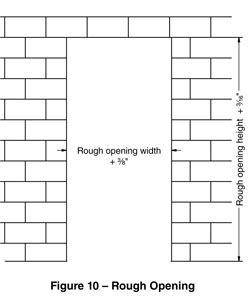
6. Existing masonry construction (see Figure 9, Figure 10, and SDI 127F)
6.1 Rough openings for existing wall, structural steel framing, or retrofit installations utilizing a butted to wall application shall be no less than 3/16˝ (4.8 mm) larger than the frame on all three sides.
6.1.1 The installer is responsible for any shimming or aligning required. Gaps are normally sealed as part of the installation or sealant/painting process.
6.1.2 Refer to Architectural specifications for the appropriate sealant material to be used at fire or smoke control doors.
6.2 Assemble frame per manufacturer’s instructions.
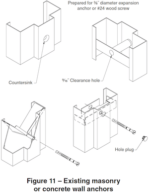
6.3 Install snap-in anchors (see Figure 11) and tap with a hammer to align with pierced holes in jambs.
6.3.1 Frames may also be supplied with anchors welded in place.
6.4 Slide frame into wall opening; install wood spreaders.
6.5 Where needed, use shims between the wall and frame at the location of anchors and spreaders to maintain squareness and alignment of frame, and to maintain door opening sizes.
6.5.1 Drill appropriate size hole (per fastener manufacturer’s instructions) for one-piece anchor bolts. Leave holes “rough” for added grip.
6.6 Insert anchor bolts and tighten securely, checking for frame alignment periodically.
6.7 Install plugs to cover bolt heads (if so equipped).
6.8 Backer rod and / or sealant shall be used where gaps occur between frame and wall.
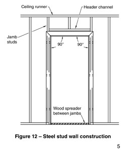
7. Steel stud wall construction, studs erected with frame (see Figure 12)
7.1 Assemble frame per manufacturer’s instructions.
7.2 Install snap-in anchors. Position anchors in frame through the throat and tap in with a hammer.
7.2.1 Frames may also be supplied with anchors welded in place.
7.3 Erect, brace, square and plumb frame as shown.
7.4 Install wood spreaders.
7.5 Attach jambs to floor through floor anchor.
7.6 Install jamb studs to floor, header channels, and ceiling runners butted tightly against frame anchors and properly positioned in frame throat for wallboard.
7.6.1 Nesting or overlapping stud joints or other wall construction practices that will increase the overall wall thickness beyond the intended finished thickness are to be avoided.
7.7 Attach jamb studs to anchors with screws or weld.
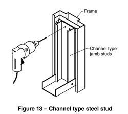
7.7.1 If using screws, drill from the back side of the stud, through both the stud and anchor, then attach with (2) screws per anchor location (see Figure 13). Screws shall be #6 x 3⁄8˝ minimum steel sheet metal or self tapping type.
7.7.2 When attaching header stud to jamb studs, be sure the stud is above frame header. This will assure ample room for attaching plaster lath or drywall and will not interfere with installation of hardware attached to frame header.
7.7.3 At wrap-around installations in fire rated walls, drywall shall extend at least 1⁄2˝ (12.7 mm) into frame throat. See Section 12 for frame installations in butted or existing stud walls.
8. Double egress frames in steel stud wall construction
8.1 Generally, the installation of double egress frames in steel stud walls follows the same procedure as Section 7.
8.1.1 If frames are supplied knocked down, assemble per manufacturer’s instructions.
8.1.2 Install anchors (if not supplied welded to frame) per manufacturer’s instructions.
8.2 Erect, brace, square and plumb frame as shown (see Figure 14).
8.2.1 Stand frame up in desired location. Anchor one jamb to floor and set wood spreader on floor from anchored jamb to loose jamb.
8.2.2 Install a vertical wood brace at center of frame.
8.2.3 Position and anchor second jamb to floor. Plumb, level and square frame, then install wood spreaders at mid-height.

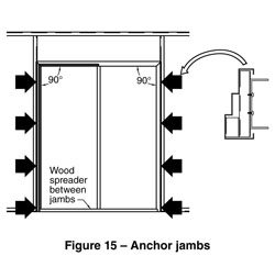
8.3 Anchor jambs (see Figure 15)
8.3.1 Install jamb studs to floor, header channels, and ceiling runners butted tightly against frame anchors and properly positioned in frame throat for wallboard.
8.3.2 Nesting or overlapping stud joints or other wall construction practices that will increase the overall wall thickness beyond the intended finished thickness are to be avoided.
8.4 Attach jamb studs to anchors with screws or weld.
8.4.1 If using screws, drill from the back side of the stud, through both the stud and anchor, then attach with (2) screws per anchor location (see figure 15). Screws shall be #6 x 3⁄8˝ minimum steel sheet metal or self tapping type.
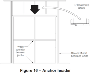
8.5 Anchor header (see Figure 16)
Header anchor requirements will vary. The manufacturer’s installation requirements should be followed.
8.6 At wrap-around installations in fire rated walls, drywall shall extend at least 1⁄2˝ (12.7 mm) into frame throat. See Section 12 for frame installations in butted or existing stud walls.
9. Wood stud construction, studs erected with frame
9.1 Assemble frame per manufacturer’s instructions.
9.2 Install snap-in anchors. Position anchors in frame through the throat and tap in with a hammer.
9.2.1 Frames may also be supplied with anchors welded in place.
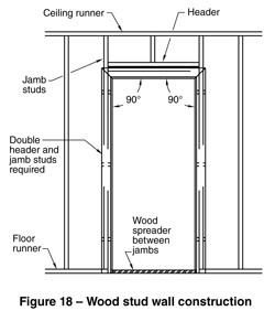
9.3 Square, brace and plumb frame as shown (see Figure 17).

9.4 Install wood spreaders (see Figure 18).
9.5 Attach jambs to floor through floor anchor.
9.6 Install jamb studs (jack stud and king stud) butted tightly against anchors and properly positioned in frame throat for wallboard (see Figure 18).
9.6.1 Attach header stud(s) or header assembly between jamb studs making sure they are above the frame head. This will assure ample room for attaching plaster lath or drywall and will not interfere with installation of hardware attached to frame head (see Figure 18).
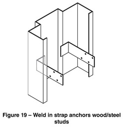
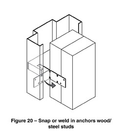
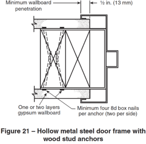
9.7 Bend anchor straps around stud leaving sufficient clearance between frame return and stud for inserting finished wall material (see Figure 19, Figure 20 and Figure 21).
9.7.1 If there is insufficient room for wall finish, notch jamb studs no more than 1/16˝ (1.6 mm) deep for anchor straps.
9.8 Square and nail top anchor to stud on ONE JAMB ONLY. Check plumb and square and continue to nail balance of anchors to stud. Repeat for opposite jamb. For steel studs install screws from back of stud into Z anchor (see Figure 22).

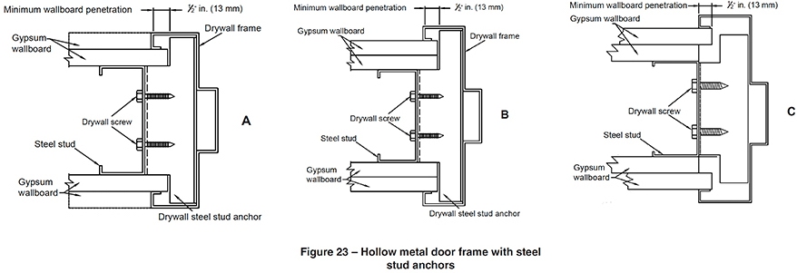
9.8.1 At wrap-around installations in fire rated walls, at least one layer of drywall on each side shall extend a minimum of 1⁄2″ (12.7 mm) into the frame throat. See Figure 23-A, B and C.
10. Wood/steel stud construction, studs erected before frame
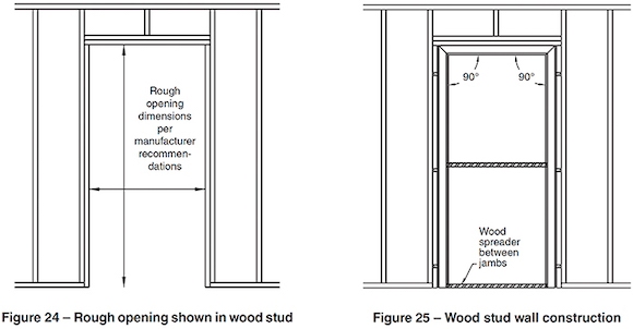
10.1 Build rough opening (see Figure 24) according to dimensions and clearances in manufacturer’s installation instructions.
10.1.1 Assure that rough openings are no less than those required in SDI 127F.
10.1.2 It is recommended that double studs be used at jambs and headers.
10.2 Assemble frame per manufacturer’s instructions.
10.3 Install snap-in anchors. Position anchors in frame through the throat and tap in with a hammer.
10.3.1 Frames may also be supplied with anchors welded in place.
10.3.2 If base anchors cannot be used add one anchor per jamb at bottom.
10.3.3 Install fire rated frames with the anchor quantity and spacing as per the individual manufacturer’s listings and instructions.
10.4 Slide frame into wall opening.
10.4.1 Install wood spreaders at bottom and mid-height. Square and level frame. Shim jambs if necessary (see Figure 25).
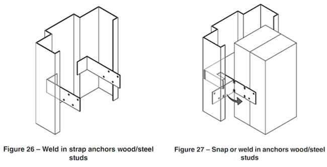
10.5 Bend anchor straps around stud leaving sufficient clearance between frame return and stud for inserting finished wall material (see Figure 26 and 27).
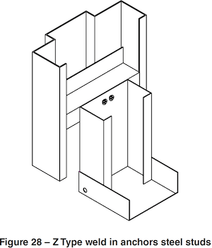
10.6 Square and nail top anchor to stud on ONE JAMB ONLY. Check plumb and square and continue to nail balance of anchors to stud. Repeat for opposite jamb. For steel studs install screws from back of stud into Z anchor (see Figure 28).
10.6.1 NOTE: At wrap-around installations in fire rated walls, at least one layer of drywall on each side shall extend at least 1⁄2″ (12.7 mm) into frame throat. See Section 12 for frame installations in butted or existing stud walls. See Figure 23-A, B and C.
11. Slip-on drywall
11.1 Prepare rough opening (see Figure 29) per frame manufacturer’s recommendations.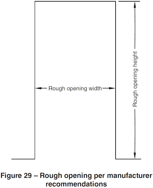
11.1.1 Nesting or overlapping stud joints or other wall construction practices that will increase the overall wall thickness beyond the intended finished thickness are to be avoided.
11.2 Install base anchors if not factory welded to jambs or if frame faces are not prepared for base anchor screws.
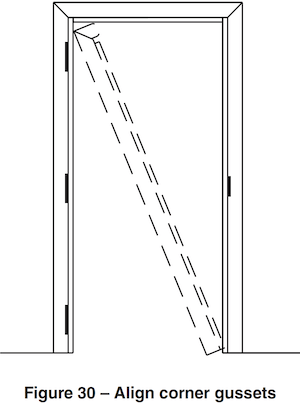
11.3 Install jambs and header onto wall per manufacturer’s instructions, taking care to align corner gussets (if so equipped). See Figure 30.
11.4 Level and square frame (see Figure 31).
11.4.1 Install wood spreaders.

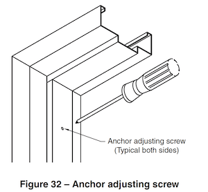
11.5 Turn adjusting screws hand tight (DO NOT USE SCREW GUN) until compression anchor contacts jamb studs (see Figure 32).
11.6 Re-check level and square. Adjust using anchor screws as needed.
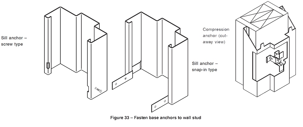
11.7 Fasten base anchors to wall stud (see Figure 33) or fasten to wall studs through prepared holes in face of jambs at bottom.
12. Butted or existing steel or wood stud wall construction
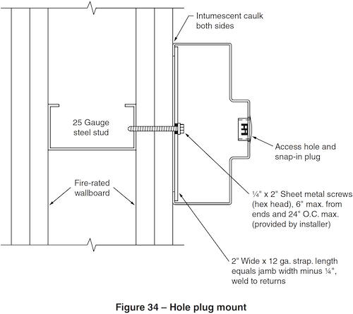
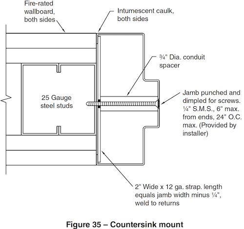
12.1 Historically, frames installed in fire-rated stud walls required frames to wrap around the wall and drywall must extend at least 1⁄2˝ (12.7 mm) into frame throat. Fire testing has confirmed that fire door frames will perform satisfactorily to the acceptance criteria of UL 10C under positive pressure when butted to new or existing stud and drywall construction (see Figure 34 and Figure 35).
12.1.1 This installation has been incorporated into NFPA 80 as Figure A.6.3.1.3(a) and A.6.3.1.3(b).
12.1.2 Applicable Building Codes and individual manufacturers’ product listings shall be consulted when these butted frames are used in fire-rated walls.
12.1.3 This installation process DOES NOT apply to Slip-on Drywall frames in Section 11.
12.1.4 Listed fill, void or cavity material shall be used at the junction of frame faces and returns with the drywall surface. The bead of fill, void or cavity material shall be no wider than 1/2˝ (12.7 mm).
12.2 Assemble knock down frames per manufacturer’s instructions.
12.3 Anchors are typically welded to frames and will either be a sleeve aligned with a countersunk hole or a plate between returns with an access hole and plug.
12.4 Assure that rough opening or opening between walls is plumb, square, and properly sized to fit overall frame dimensions and expansion capability of intumescent caulk or sealant. (See SDI 127F for further information).
12.5 Using a “stud finder” or similar tool, assure that studs will align with frame mounting screws.
12.6 Slide frame into wall opening; install wood spreaders at the floor and mid-height of opening.
12.7 Use tapered shims between anchors and wall and spreaders to maintain squareness and alignment of frame and to maintain door opening. Make sure that shims will not interrupt the sealant.
12.8 Insert 1⁄4˝ (6.4 mm) sheet metal screws of suitable length to engauge studs through countersink or access hole in frame (see Figure 34 and Figure 35) and tighten securely. Check for frame alignment periodically. (Frame profiles shown are for general details only. Anchors and profiles may vary).
12.9 Insert plugs to cover access holes if so equipped.
12.10 Install listed intumescent caulk or sealant around perimeter of frame, making sure to cover any gaps caused by irregularities in walls.
Annex A (informative)
Manufacturing Tolerances for Standard Steel Doors and Frames
A1. Introduction
It is the intent of this publication to inform users of standard steel doors and frames with definitive information regarding manufacturing tolerances. It is also intended to inform the installation contractor(s) of the tolerances to be considered to assure proper operation of the complete opening. It is intended for in-plant inspections. It may be used for on-site inspections where there is no evidence of damage to material or improper installation.
The information contained herein pertains to doors and frames manufactured in accordance with ANSI A250.8, Recommended Specifications for Standard Steel Doors and Frames. It is not intended to have reference to special or unusual door and frame conditions.
A2. Reference Documents
- ANSI/SDI A250.8 (SDI 100) – Recommended Specifications for Standard Steel Doors & Frames
- ANSI/SDI A250.6 – Recommended Practice for Hardware Reinforcings on Standard Steel Doors and Frames
- ANSI/SDI A250.7 – Nomenclature for Standard Steel Doors & Steel Frames
- ANSI/SDI A250.3 – Test Procedure & Acceptance Criteria for Factory Applied Finish Coatings for Steel Doors & Frames
- ANSI/SDI A250.10 – Test Procedure & Acceptance Criteria for Prime Painted Steel Surfaces for Steel Doors & Frames
- ANSI/BHMA A156.115-2006 – Hardware Preparation in Steel Doors and Steel Frames
- ANSI/BHMA A156.115-W-2006 – Hardware Preparation in Wood Doors with Wood or Steel Frames
- ASTM A568-09 – Standard Specification for Steel, Sheet, Carbon, Structural, and High-Strength, Low-Alloy, Hot-Rolled and Cold-Rolled, General Requirements for
- ASTM A653-10 – Standard Specification for Steel Sheet, Zinc-Coated (Galvanized) or Zinc-Iron Alloy-Coated (Galvannealed) by the Hot-Dip Process
- ASTM A924-10 – Standard Specification for General Requirements for Steel Sheet, Metallic- Coated by the Hot-Dip Process
- NFPA 80 – Standard for Fire Doors and Other Opening Protectives
- SDI 122 – Installation and Troubleshooting Guide for Standard Steel Doors and Frames
A3. Materials and Finishes
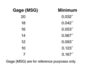
A3.1 Steel Thickness: Manufacturers no longer order sheet and coil to a specific gauge, but rather to a minimum decimal thickness. This thickness is the lowest of the range for a specific gauge. The steel supplier is therefore permitted to exceed, but not be less than the specified decimal thickness. These minimum values meet the stringent requirements of both Underwriters Laboratories Inc. and ITS/Warnock Hersey. Examples of
minimum allowable steel thickness:
A3.2 Steel Coatings
Thickness of metallic coatings (generally zinc) are defined by ASTM A924, Standard Specification for General Requirements for Steel Sheet, Metallic-Coated by the Hot-Dip Process and A653, Standard Specification for Steel Sheet, Zinc-Coated (Galvanized) or Zinc-Iron Alloy- Coated (Galvannealed) by the Hot-Dip Process. The two most commonly used are designations A40 and A60. Minimum requirements for these designations are:
- A40 = 0.40 oz/ft2 total both sides.
- A60 = 0.60 oz/ft2 total both sides. For reference, 1 oz/ft2 = 1.7 mils thickness.
A3.3 Factory Applied Coatings
Since factory applied coatings (primer, finish paint, etc.) are subject to performance standards rather than thickness, the dry film thickness is irrelevant. Such coatings must comply with performance criteria of:
ANSI/SDI A250.3 – Test Procedure and Acceptance Criteria for Factory Applied Finished Painted Steel Surfaces for Steel Doors and Frames
OR
ANSI/SDI A250.10 – Test Procedure and Acceptance Criteria for Prime Painted Steel Surfaces for Steel Doors and Frames.
A4. Frame Tolerances
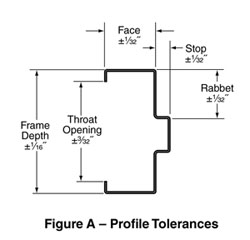
A4.1 Frame Cross Section Profile
Permissible tolerances in frame profile surfaces are as shown in Figure A.
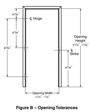
A4.2 Frame Opening & Vertical Locations
A4.3 Bow or Twist of Jambs or Header
Realizing that frames are somewhat “pliable”, and require bracing and alignment during installation, allowable deformation (bow, twist, etc.) of jambs or header of frame prior to installation shall not result in a reduction of opening sizes more than 1/16˝ beyond those shown in Figure B when measured at any point.
A4.4 Horizontal Alignment of Door Within Rabbet
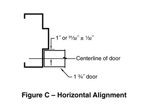
Hinge and strike backsets shall allow the horizontal centerline of the door to be in line with the horizontal centerline of the frame rabbet ± 1/32˝ prior to installation. Figure C is an example based on a 1 3/4˝ door in a 1 15/16˝ rabbet.
4.5 Frames With Lights or Panels
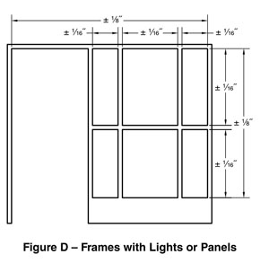
Opening sizes (width or height) for side or transom lights or panels and for borrowed light frames shall be subject to a tolerance of ± 1/16˝ for each individual light or panel. These tolerances shall be non-accumulative so that the overall frame opening sizes are not increased by more than 1/8˝ (see Figure D).
A5. Door Tolerances
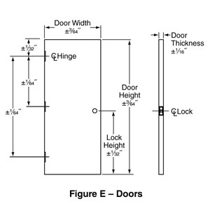
A5.1 Door Size, Thickness, and Vertical Locations (see Figure E)
A5.2 Door Squareness
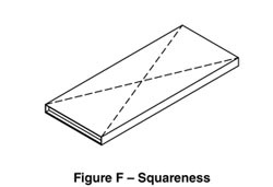
When measured diagonally (see Figure F) from corner to corner along the same face, the measurements shall be within 1/16˝ of each other.
A5.3 Door Perimeter Flatness
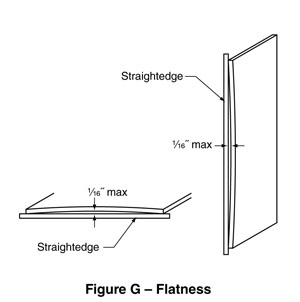
When a suitable straightedge is laid against the door face at or within 1/4˝ of the top, bottom, hinge edge, and lock edge on both faces any deviation between the face and the straightedge shall not allow a 0.0625˝ rod or block to pass (see Figure G). Note: The straightedge shall be allowed to “rest” naturally on the door surface, not pulled down at one end to meet the door.
A5.4 Door Face Bow or Crown
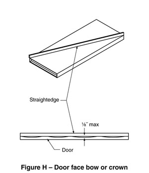
# When a suitable straightedge is laid diagonally against the door face at least 1/2˝ from corners any deviation between the face and the straightedge shall not allow a 0.125˝ rod or block to pass (see Figure H). Note: The straightedge shall be allowed to “rest” naturally on the door surface, not pulled down at one end to meet the door.
A5.5 Door Twist
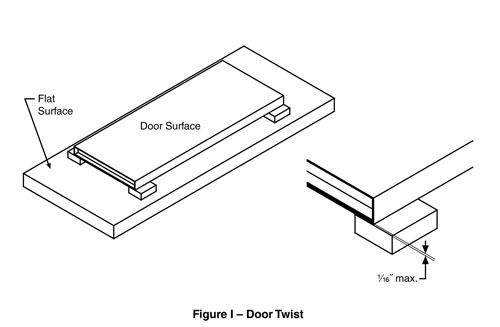
The door is laid onto a suitable, flat fixture or surface that is free of any warp, bow, or twist. Support blocks of identical heights shall be inserted between the fixture and the door face at all four corners of the door. Any deviation between the face and the support blocks shall not allow a 0.0625˝ rod or block to pass (see Figure I). Note: The door shall be allowed to “rest” naturally on the support blocks, not pulled down at any corner to meet the blocks.
A5.6 Doors With Lights or Panels
Opening sizes (width or height) for lights or panels cut into doors shall be subject to a tolerance of ± 1/16˝ for each individual light or panel.
A6. Hardware Preparations
A6.1 Vertical Locations
Tolerances for vertical locations are as noted in Paragraphs A4.2 and A5.1.
A6.2 Horizontal Alignment
Tolerances for horizontal alignment of door and rabbet are as noted in Paragraphs 4.4.
A6.3 Mortise Depth
The depth of hardware items mortised into edges of doors (such as hinges, strikes, lock fronts, flushbolts) shall be as defined on manufacturer’s templates and/or ANSI A156.115 documents subject to an additional tolerance
of ± 1/64˝
A6.3.1 Cutout Depth at Frame or Door Faces
In order to allow for field adjustment, usually accomplished by shimming, hardware cutouts (such as hinges) that extend from door edges around to faces or from frame rabbet around to faces are allowed to exceed mortise depth by 1/16˝. See Paragraph A7 for examples of common hinge shimming procedures.
A6.3.2 Depth For Recessed or Concealed Hardware
The depth for hardware items recessed into top or bottom of doors or edges of doors (such as pocket pivots, floor closers, top pivots, concealed closers or holders, etc) shall be as defined on manufacturer’s templates subject to an additional tolerance of +1/16˝, –0˝. Notches in door faces shall have similar tolerances.
A7. Frame Installation And Door Adjustments
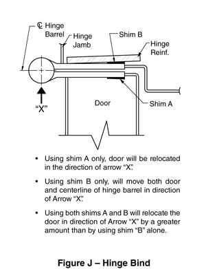
A7.1 Adjusting Pivot Point by Shimming
Providing extra depth along door or frame faces allows for hinge knuckles to be offset, thus changing the pivot point of the opening. Shims are usually thin strips of 1/4˝ wide material approximately equal to the hinge height.
A7.1.1 Figure J shows how to relocate the pivot point toward the jamb.
7.1.2 Figure K shows how to relocate the pivot point away from the jamb.
A7.2 Frame Installation Tolerances
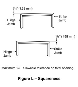
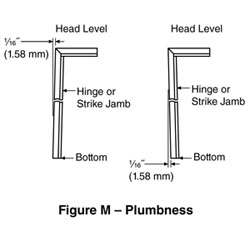
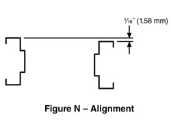
While this document is mainly concerned with tolerances relating to the manufacturing process, openings will not function properly if the frame is not installed within recognized tolerances. Figures L, M, N, and O show examples of the accuracy to be maintained while setting frames.
A7.3 Troubleshooting
Further information regarding corrective actions for of door & frame openings may be found in SDI-122.


Annex B (informative)
Installation Exceptions
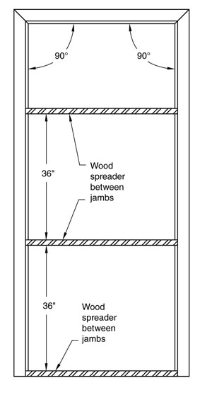
The installation instructions contained in ANSI A250.11 are intended to apply to most typical frame installations. There are, however, certain types of frames for which additional wood spreaders are recommended during the frame installation to ultimately assure the proper door operation.
Three-sided frames with face dimensions of 1-1/2˝ or less of any opening size, frames for doors that weigh over 9 lbs. per square foot and/or frames of heights greater than 8′-0˝ are more prone to variations in installed tolerances. Under most conditions, frames such as these require more support during the installation process.
For installations such as these, the SDI recommends the use of wood spreaders at the bottom of frames AND at 36˝ intervals between the top and bottom as indicated in the illustration below.