Recommended Details for Standard Steel Doors, Frames, Accessories and Related Components
SDI 111
View PDF
Table of Contents
- 111A-24 Recommended Standard Steel Door Frame Details
- 111B-24 Recommended Standard Details for Dutch Doors
- 111C-24 Recommended Louver Details for Standard Steel Doors
- 111D-24 Recommended Door, Frame and Hardware Schedule for Standard Steel Doors & Frames
- 111E-24 Recommended Guidelines for the Use of Gasketing and Thresholds for Standard Steel Doors & Frames
- 111F-24 Recommended Existing Wall Anchors for Standard Steel Doors & Frames
- WITHDRAWN: 111G Recommended Standard Preparation for Double Type (Interconnected) Locks on Standard Steel Doors & Frames
- 111H-24 High Frequency Hinge Preparations for Frames
- 111I-24 Cast In Place Hollow Metal Frames
- 111J-25 Recommended Glazing for Exterior Hollow Metal Doors
NOTE: To reduce the visual clutter of providing both United States customary units of measurement (US) and International System of Units (SI), this standard will present all measurements in only the US units.
111A-24 Recommended Standard Steel Door Frame Details
Hardware Locations
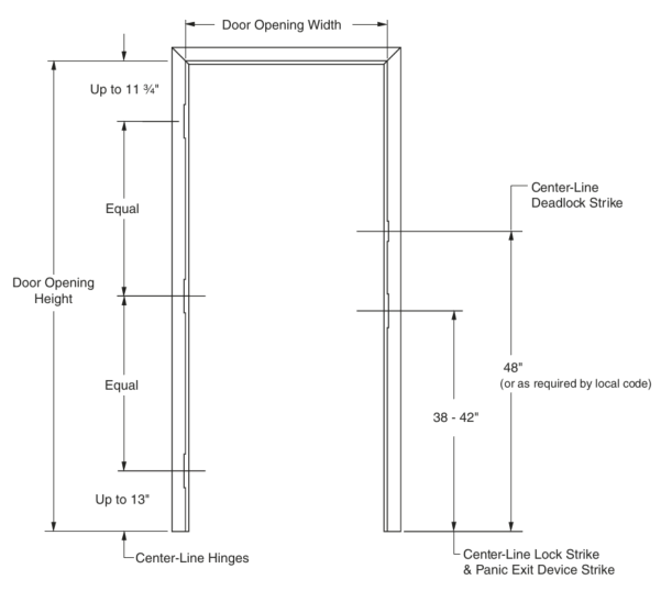
Note: Center Hinge Omitted on 6′ 8″, 1 3/8″ Non-Rated Doors, Unless Specified.
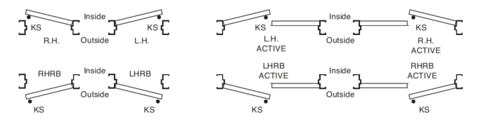
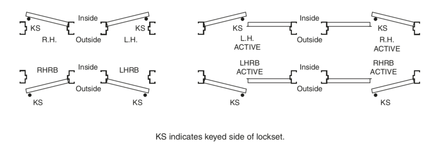
Handing Chart
Note: All values which do not carry specific tolerances or are not marked maximum or minimum shall have the following tolerances: Linear dimensions shall be ± 1/16 in. Weight or force shall be ± 2%. Angles shall be ± 2 degrees. Where only minus tolerances are given, the dimensions are permitted to be exceeded at the option of the manufacturers.
Standard Frame Details
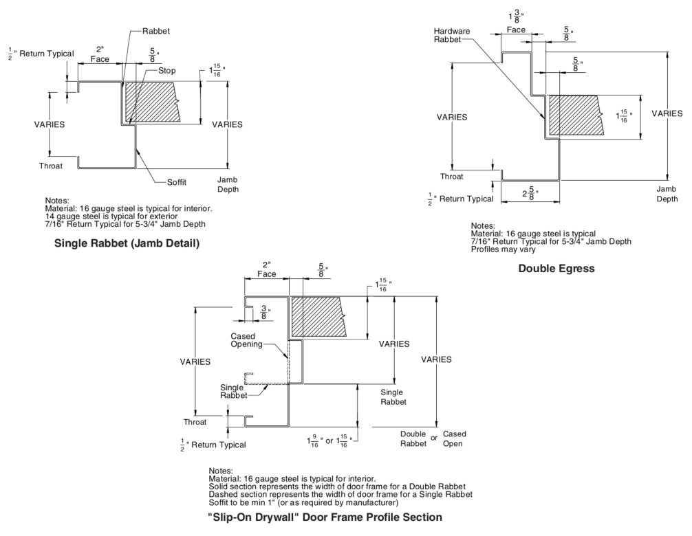
Standard Profiles

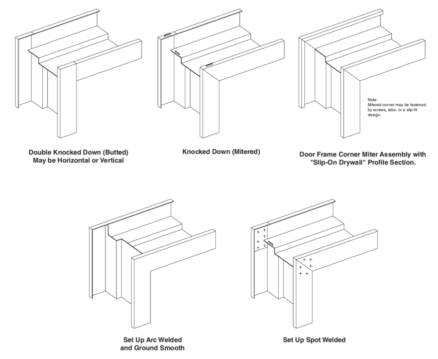
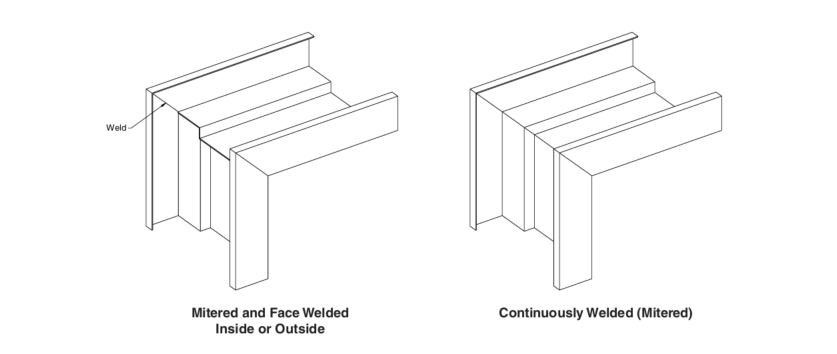
Corners
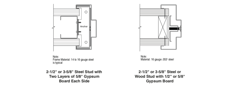
Common Wall Conditions
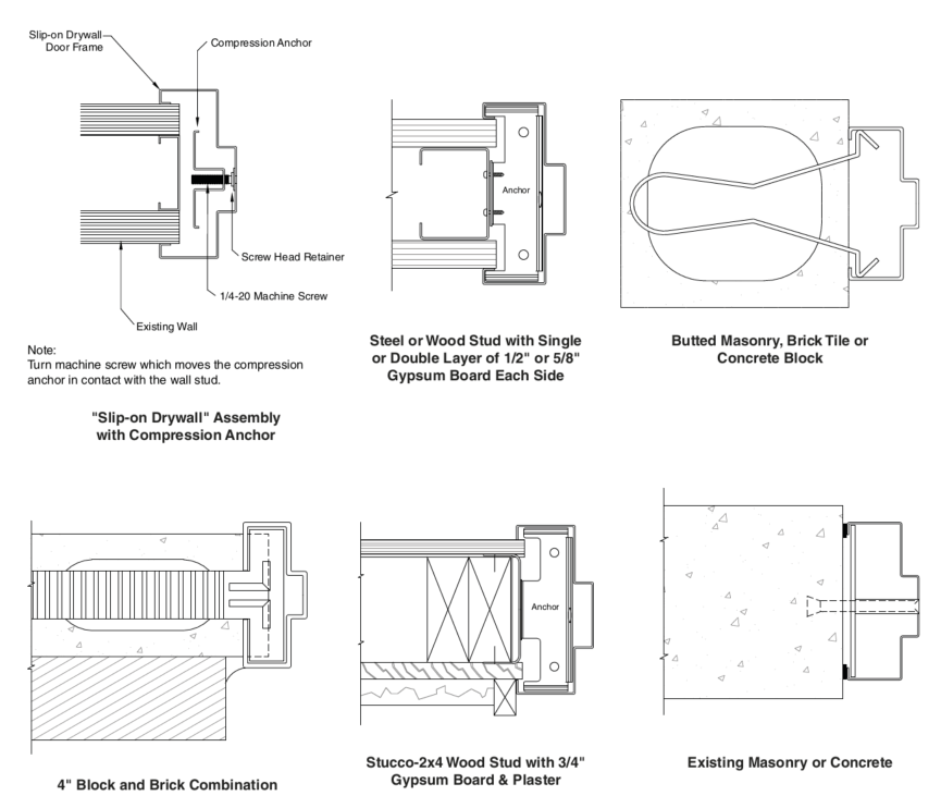
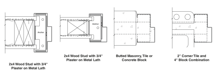
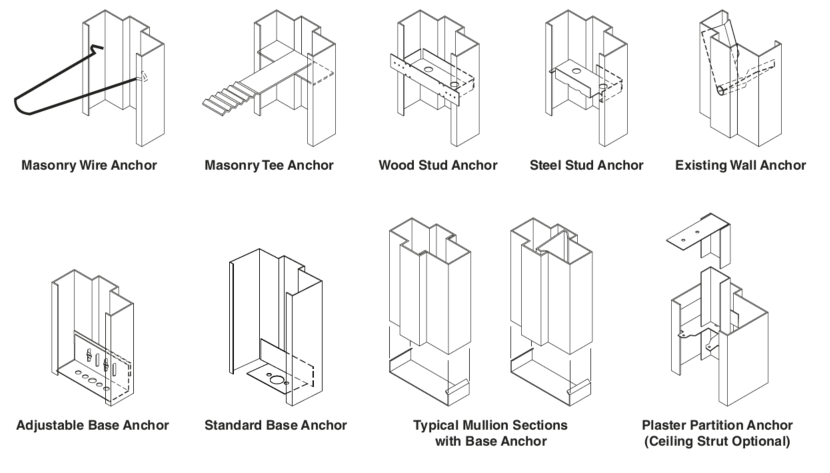
Anchor Details
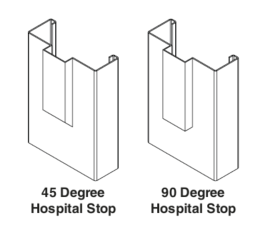
Hospital Stop Details
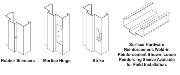
Hardware Preparations
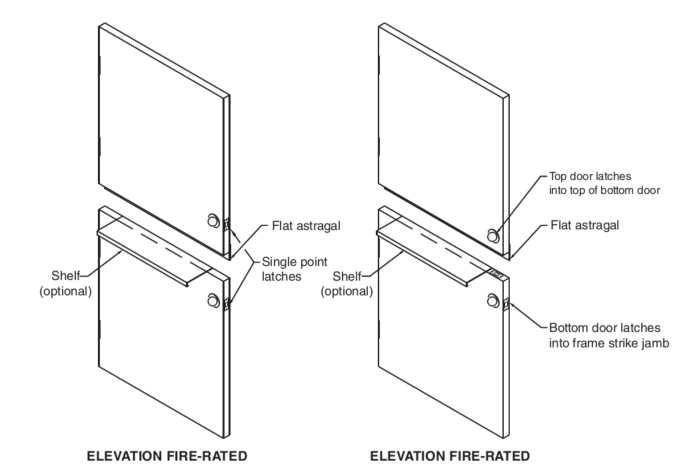
111B-24 Recommended Standard Details for Dutch Doors

Note: All values which do not carry specific tolerances or are not marked maximum or minimum shall have the following tolerances: Linear dimensions shall be ± 1/16 in. Weight or force shall be ± 2%. Angles shall be ± 2 degrees. Where only minus tolerances are given, the dimensions are permitted to be exceeded at the option of the manufacturers.
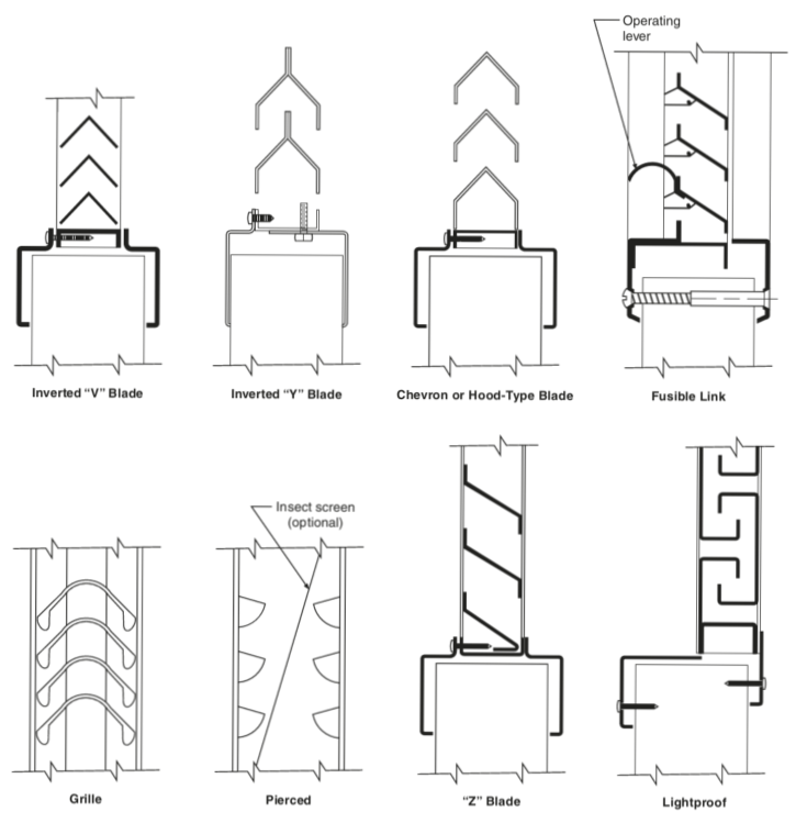
111C-24 Recommended Louver Details for Standard Steel Doors
Standard steel doors can be provided with a variety of louver designs and sizes. This publication contains explanations and details of louver designs that are most commonly available within the standard door industry.
When specified, doors shall be provided with louvers at the bottom and/or top. The choice of which to use must be determined by the architect on aesthetic, functional, and economic grounds.
Function – Louvers permit free air passage, controlling the volume by their size or design. They diffuse or control direction of air flow by blade design.
Insert louvers – Louvers commonly used in standard steel doors are of the “insert” type designed to be mounted into a cutout in the door and an overlapping frame. Inverted “V” blade, “Z” blade, inverted “Y” or chevron-type blade, lightproof, adjustable blade, grille type, and fusible link self-closing fire door types are available in a wide range of sizes. Also available from some steel door manufacturers is a pierced louver design. Insert louvers intended for exterior doors or other doors where security is a consideration should have fasteners or materials specified accordingly.
Note: If a louver door is required to provide security, the steel door manufacturer should be consulted.
Bird or insect screens are available with many of the standard design louvers. Where specified, consult steel door manufacturer for availability.
Weatherproof louvers – True weatherproof designs do not exist. Some louvers are manufactured to provide a certain degree of rain protection.
Louver construction – Standard louver frames are a minimum 20 gauge steel with louver blades of a minimum 24 gauge steel. The louver blades can be welded or tenoned to the frame and the entire assembly is generally fastened to the door with moldings. Generally, one molding will be an integral part of the louver, while the other molding will be detachable. When louvers are installed, the detachable moldings should be located on the room or non-security side of the door. Where doors are manufactured as nonhanded, louvers may require reversing during door installation to suit actual handing.
Application:
Inverted “V” or “Z” blade types allow maximum free air flow with minimum static pressure differential.
Inverted “Y” or chevron blade types, while offering less free air flow, offer a higher strength factor for schools and other areas where vandalism or hard usage may occur.
Lightproof louvers are used where light transmission must be avoided, but provide minimal free air flow.
Adjustable blade louvers are used where air flow is varied in velocity and control of flow is needed.
Grille type louvers are normally associated with air conditioning, where air must be diffused in random flow, avoiding higher velocity air flow patterns.
Fusible link louvers are used in fire doors where flames and intense heat passage must be controlled. The link release temperature recommended is 135°F (57°C). These louvers must be labeled and may not exceed 24˝ x 24˝. Fusible link louvers are allowed only at the bottom of fire doors. Since closing is heat activated, these louvers are not to be used on smoke control doors.
Pierced louvers, available from some steel door manufacturers, offer a flush condition and may be furnished with internal insect screens. Louvers are formed by embossing the door face sheets.
Louver size determinations – As a guide, the following approximate percentages of louver size may be used to determine the free area in a given size louver:
- Pierced louver 20%
- Inverted “V” inserted louver 50 – 60%
- Inverted “Y” (chevron) inserted louver 40 – 60%
- “Z” type inserted louver 40 – 45%
- Adjustable inserted louver 40 – 50%
- Lightproof inserted louver 20%
- Fusible link inserted louver 45%
The above percentages assume there is no air pressure drop from one side of the door to the other. On air condition grilles an air pressure drop is normal. An average 70% of the grille size can be used in computing free area on doors with air condition grilles.
The percentages noted above are approximates. Consult the individual manufacturer’s literature for the specific sizes and ratings normal to their program.
Coordination – A combination of glass lights and louvers is common in steel door work. Care should be taken to avoid specifying too long a narrow light when a louver or grille occurs in the bottom of the same unit. In addition, handicap codes may dictate the location of the louver relative to the bottom of the door.
Full louver doors – A minimum 5˝ rail occurs at the top and at the vertical stiles and an 8˝ minimum rail occurs at the bottom of these doors (Consult door manufacturer for exact stile/rail dimensions). Stile and top rail sizes must be coordinated with closer dimensions, lock preparations, and lever handles. Pierced louvers are not available on full louvered doors.
Finish – The finish is to be prime painted, except when the louver is used in a factory prefinished door, in which case the louver will be finish painted with a color to match the door. For exterior doors, zinc coated louvers are available where specified.
Cross Section Details
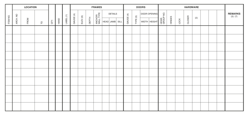
111D-24 Recommended Door, Frame and Hardware Schedule
for Standard Steel Doors & Frames
The purpose of this publication is to establish a guide for architects and those responsible for scheduling doors, frames, and hardware requirements.
Although primarily designed for steel doors and frames, this suggested schedule is flexible enough to list total door and frame requirements of a complete job.
Items not specifically covered in the schedule may be listed in the “Remarks” and extra columns near the end.
Typical handing of doors and hardware is to be based on the format below.
Note: While the term ‘gauge’ is no longer common for defining material thickness it is still used to specify doors and frames for ordering purposes. The term ‘thickness’ is used when defining the actual dimension of an item, and the term ‘gauge’ is used in the context of specifying a particular door or frame.
Handing Chart
Door, Frame and Hardware Schedule
General Notes:
- If a fire door is required, it is to be designated in the “Label” column of schedule with appropriate hourly rating. Also, note in the “Remarks” column whether door is to have a UL Solutions, Intertek (ITS)/Warnock Hersey or FM Global label.
- Thresholds, when required, are to be noted in “Hardware” column of schedule.
- Any special item not listed in schedule for doors, frames, or hardware is to be shown in the “Remarks” column.
- Indicate gauge of material for steel. When materials other than steel are used, indicate AL for aluminum or WD for wood.
- Refer to SDI-134 for recommended standard door design nomenclature.
- When frame elevations are indicated, supplemental drawings must be attached.
- Doors provided with 3/4″ undercut unless otherwise specified.
111E-24 Recommended Guidelines for the Use of Gasketing and Thresholds
for Standard Steel Doors & Frames
The following details represent the recommendation of the Steel Door Institute in this important corollary area. This document should in no way be considered an endorsement of any manufacturer nor does it imply that any materials not shown should be considered inferior weatherstripping. The criteria employed in the selection of these details included:
- The experience of the Institute with the details shown.
- The adaptability of the material shown to standard steel doors and frames.
- The ability to maintain gasketing at the door and frame during periods of normal thermal movement to the balance of the building structure.
- The availability of the material from normal commercial sources.
- Ease of maintenance.
General
Gasketing and thresholds are used to control the flow of air, smoke, heat or cold, water, sound or other environmental factors through the door opening. The location or intended use of the door assembly, the environment to which it is exposed, and the performance expected will dictate the selection of gasketing and threshold products.
The variety of materials, their composition, profiles, and performance are virtually limitless. These are described in ANSI/BHMA A156.21 or A156.22. Generally, gasket materials are sponge neoprene, rubber, vinyl, brushes, or magnets. Retainers are generally steel, aluminum, brass, bronze, vinyl, or other non-ferrous materials. Information in catalogs published by BHMA members aid in the selection of perimeter sealing “ systems” to meet the applicable performance criteria of the door assembly.
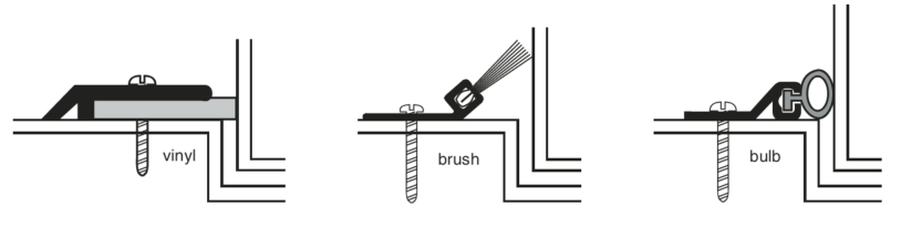
Perimeter Seals
Sealing of gaps between door edges and the header or jambs generally has the greatest effect on performance of the door opening. The available options are as varied as their applications and their mounting surfaces e.g. steel, structural steel, or wood. Care should be taken to select materials that will assure performance under specific job requirements as well as meeting the mounting surface criteria.
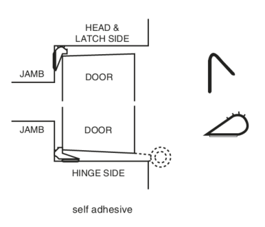
Gasketing products should never impede the operation, opening or closing of the door assembly. Simple contact is all that is required for some products. Other products for more severe installations require a slight compression. A simple test for gasket compression may be conducted by inserting a sheet of letterhead paper into the gap and closing the door. The paper should be held in place by the gasketing.
Gasketing or weather-stripping, of any kind, should be furnished and installed in accordance with manufacturer’s instructions.
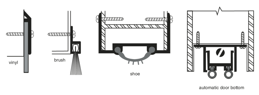
Door Bottom Seals
In most instances, sealing of gaps between the bottom of doors and flooring or thresholds is accomplished with door bottoms or overlapping strips in metal retainers. These may be of a design that extends beyond the bottom of the door mechanically, or of a fixed protruding or overlapping design.
Door bottom gaskets must compress against a solid object to affect a proper seal. Carpeting by its pliant nature does not provide a proper seal.
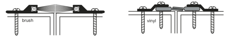
Astragal Seals
Sealing of door edges at meeting stiles, in lieu of or in addition to factory mounted astragals is accomplished by supplemental gasketing. This gasketing may be closely abutting fixed members or by overlapping strips in metal retainers.
Overlapping gasketing is normally used to avoid interference with edge mounted hardware such as locksets or flush bolts. Closely abutting gasketing is commonly used where both doors must operate simultaneously or independently as in egress doors.
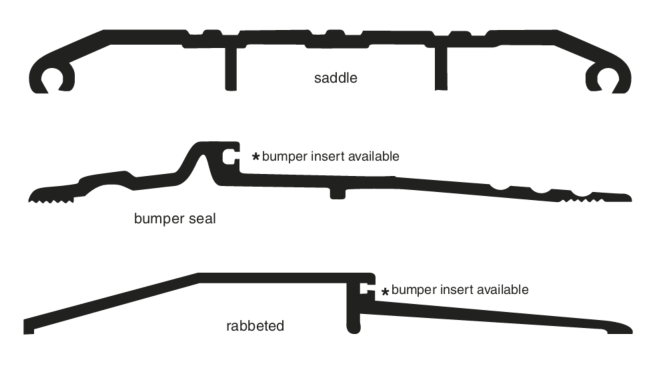
Thresholds
Thresholds may be used in addition to or in lieu of door bottom seals. They may incorporate gaskets or other formed profiles to allow for exit device latching or may be prepared for flush bolt latching. Thresholds should be provided under the door and between the frame to allow for a smooth transition between floor coverings of different heights or materials. Special consideration should be given to threshold designs used in means of egress or in handicap accessible situations. The latter limitations are covered in ANSI/ICC A117.1.
Fire Door Considerations
When supplying products to be used on fire rated openings, care should be taken to maintain the proper clearances around the perimeter of the door assembly in accordance with NFPA 80. Gasketing materials must be investigated or “Listed” to determine that their installation does not adversely affect the fire resistance performance of the assembly. For example, the performance of gasketing is observed during the fire test to ensure that flaming does not occur on the exposed surface of door assemblies. It is important to note, however, that the ANSI/UL 10B, ANSI/UL 10C and ANSI/NFPA 252 standard fire tests do not include evaluation of the door assembly relative to preventing the passing of smoke or other products of combustion through or around the assembly. Openings that require a smoke seal must be tested in accordance with NFPA 105 or UL 1784. In fire door applications it is VITAL that gasketing does not inhibit the ability of the door assembly to close and latch.
Performance Testing Criteria
Gasketing products are covered under ANSI/BHMA A156.22. Included in that standard are:
- Closing Force Test
- Heat Test
- Cold Test
- Energy Test
- Intumescent Test
- Acoustic Test
- Smoke Infiltration Test
Thresholds are covered under ANSI/BHMA A156.21. Included in that standard are:
- Weight Bearing Test
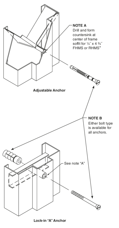
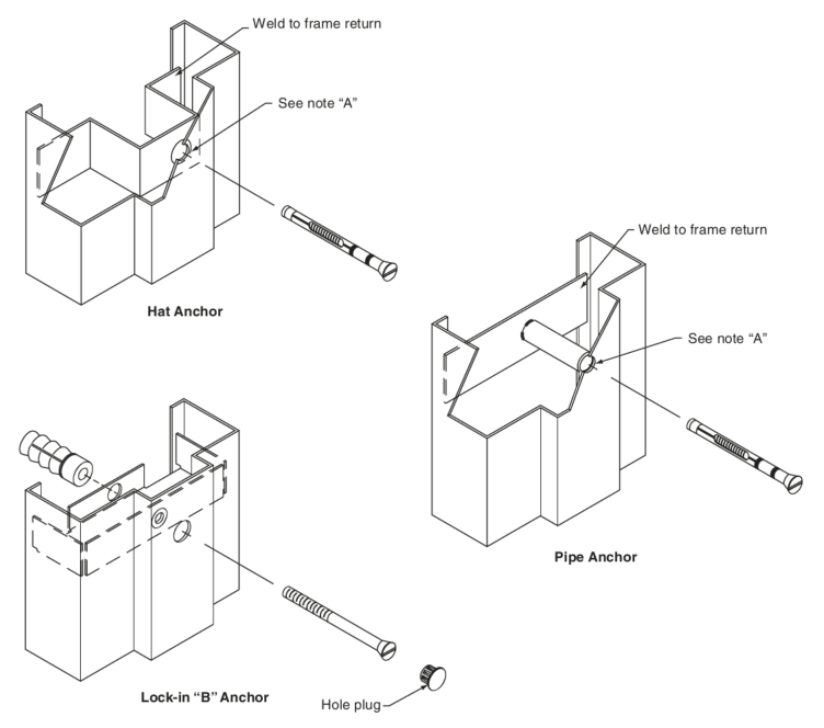
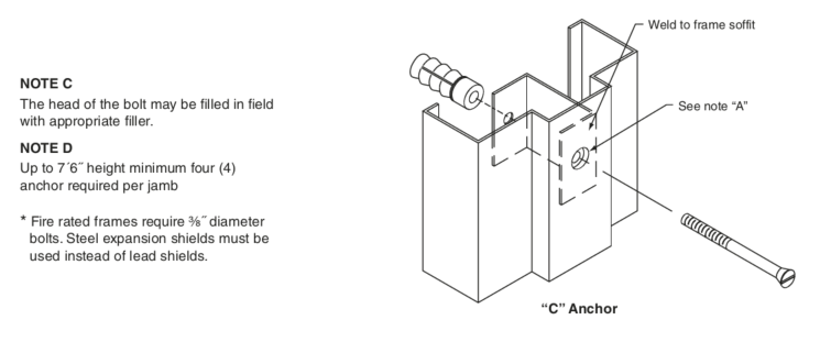
111F-24 Recommended Existing Wall Anchors
for Standard Steel Doors & Frames
This standard is a guide for architects to help them recognize available options to the traditional sub buck detail widely used in the past. The anchoring systems shown are available in regular and labeled frames.
The details shown are typical of those employed by members of the Steel Door Institute, but all of the details are not made by all of the members of the Institute. A general reference to this document in your specifications should result in all of the members of the SDI and most of the non-members being able to bid on the job without a multitude of exceptions.
In order to make the installation successful, careful consideration shall be given to all tolerances involved and that sufficient clearance is figured to allow for them.
It has been “customary” to allow 1⁄4˝ clearance around the frame perimeter when establishing rough opening sizes or when figuring non-standard overall frame sizes. Although this dimensional requirement does not appear in Industry publications, it is based on the following:
- Both SDI 117 and ANSI/NAAMM HMMA 861 recognize a + tolerance in opening width and height.
- Both of these documents recognize a ± tolerance in frame face dimensions.
- Both ANSI/NAAMM HMMA 861 and SDI 117recognize a ± installation tolerance for vertical plumb.
Frames will “fit and function” if made to these dimensional tolerances and installed within tolerances.
There is, however, relatively no assurance that the substrate (walls) will be of suitable size or alignment.
We therefore recommend that the rough openings for these cases be no less than 3/16˝ larger on all 3 sides than the “intended” overall frame size. (Example: 3070 standard frame = 3´-4 3⁄8˝ x 7´-2 3/16˝). The installer carries the responsibility for shimming and aligning as necessary. Gaps are normally sealed as part of the installation or caulking/painting process. Architectural Specifications are to be consulted to determine the appropriate sealant material to be used at fire door or smoke control frames.
111H-24 High Frequency Hinge Preparations for Frames

Background:
There are occasions where steel frames used in extremely high frequency or high use areas need to be supplied with additional reinforcing to eliminate potential door sag. These types of openings would include: main entrances to schools, rear exits where severe wind abuse could be a factor, auditoriums, gymnasiums, and the like. When these types of installations are required, there is a method in which this can be handled, efficiently and economically, through providing auxiliary reinforcing to standard door frames. The specification for this is as follows:
Specification:
When a high frequency preparation is required, the top hinge of the door frame shall be provided with an auxiliary reinforcement as shown in example ‘A’ or ‘B.’ For additional strength, the center and bottom hinge reinforcement may also be provided with additional reinforcements.
* High frequency hinge preparations may vary between manufacturers.
111I-24 Cast In Place Hollow Metal Frames
When cast in place frames are not an option, a rough opening should be blocked out no less than 3/16″ larger than the frame on all three sides. For example, the opening for a 3′ 0″ x 7′ 0″ standard frame with 2″ faces would be 3′ 4-3/8″ x 7′ 2-3/16″ minimum. The installer is responsible for anchoring the frame per the manufacturer’s installation instructions, shimming, and aligning as necessary.
111J-25 Recommended Glazing for Exterior Hollow Metal Doors
Glazing Hollow Metal Doors for Exterior Glass Lights
The following details represent recommendations for standard glazing for non-labeled exterior door applications.
Standard steel doors can be provided with a variety of glass light designs and sizes. Proper installation of light kit, glass and glazing materials is essential when designed for exterior applications, following the correct method of installation will help prevent water and air infiltration at exterior hollow metal door locations.
Whether a light kit is being glazed in the field or at the manufacturer, the glazing installer must follow the light kit or door manufacturer’s installation instructions for best performance against water, thermal, and wind elements.
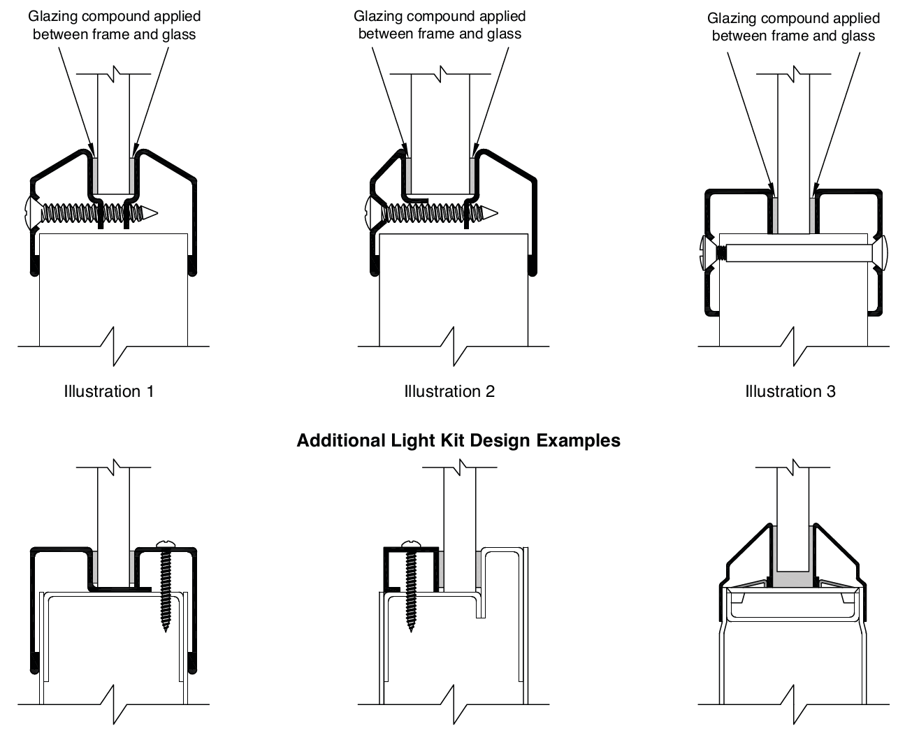
The following instructions and illustrations are examples of glazing requirements and locations for glazing tape or sealant.
- Apply glazing tape/compound around entire light kit or glass perimeter on both sides as shown (Illustrations 1, 2 & 3). There should be no gaps at meeting edges of glazing tape.
- Insert blank (secure) side of light kit in door cutout. Lay in glass with glazing tape applied. Place inner light kit frame in door cutout and secure with screws provided.
- Visually inspect perimeter of glass and glazing to insure that contact is made and there are no gaps or openings between light kit and glazing material.
- For added weatherproofing, installer may apply additional sealant around perimeter of light kit at meeting edge or underneath light kit between light kit frame and door surface.