American National Standard
Recommended Practice for Hardware Reinforcing on Standard Steel Doors & Frames
ANSI/SDI A250.6-2024
View PDF
Table of Contents
- General
- Purpose
- Scope
- Reinforcing Methods
- Reference Documents
- Recommended Reinforcing Thickness
- Recommended Application of Hardware
- Mortised Hardware
- Field Drilling and Tapping
- Thru-Bolting
- Sheet Metal Screws
- Continuous Hinges
Tables
Figures
- Examples of equivalent reinforcing methods
- Full #12-24 threads
- Extrusion to create (3) full threads of #12-24
- Maintain a minimum of 65% of full thread
- Full thread shall not fall below 65%
- Proper thru-bolting
- Improper thru-bolting
Appendices
1. General
1.1 Purpose
It is the intention of this publication to furnish users and prospective users of standard steel doors and frames with practical information regarding accepted design methods for reinforcing and recommended practices for proper field preparation for builders’ hardware.
1.2 Scope
The information contained herein pertains to doors and frames manufactured in accordance with ANSI/SDI A250.8 Specifications for Standard Steel Doors and Frames published by the Steel Door Institute. It is not intended to reference architecturally specified or specialized situations beyond the scope of this document or documents herein.
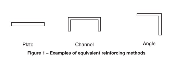
1.3 Reinforcing Methods
This standard recognizes as equal a variety of reinforcing methods produced by unique manufacturing processes. These processes include forming options (see figure 1) or integral gussets or fillets on lighter gauge members to achieve strength and performance equal to heavier gauge members.
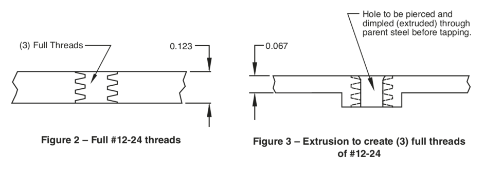
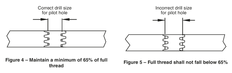
1.3.1 — Where reinforcements require tapping for machine screw threads, an equivalent number of threads may be rendered in a lighter gauge part with a pierced and dimpled (“extruded”) hole as compared to a heavier gauge part manufactured with conventional processes. For example, equal thread depth can be achieved on a piece of 0.067″ metal and on a flat plate of 0.123″ metal (see figures 2 and 3). The extrusion process results in equal strength, pull-out strength, equivalent number of threads and a lighter weight than the parent metal or equivalent flat reinforcing plate.
2. Reference Documents
- ANSI/SDI A250.4 Test Procedure and Acceptance Criteria for Physical Endurance for Steel Doors, Frames, and Frame Anchors
- ANSI/SDI A250.8 Recommended Specifications for Standard Steel Doors and Frames
- Machinery’s Handbook
3. Recommended Reinforcing Thickness
The Manufacturer, based on individual construction methods and tooling capabilities, shall reinforce their product to ensure performance in accordance with ANSI/SDI A250.4. This reinforcing shall include (unless noted otherwise) reinforcing and tapped mounting holes for template hinges and ANSI defined locks as specified. Additional reinforcing for surface applied hardware shall be built into the door at the factory when specified.
As a guide to specification writers, table 1 shows the minimum thickness of steel to be used for hardware reinforcing as endorsed by ANSI/SDI A250.8.
Table 1 – Minimum Hardware Reinforcing Thickness
| Hardware Item | Door | Frame | ||
|---|---|---|---|---|
| inches | MSG No.(6) | inches | MSG No.(6) | |
| Mortise Hinge 1-3/8″ Door(1) | 0.093 | 12 | 0.093 | 12 |
| Mortise Hinge 1-3/4″ Door(1)(2) | 0.123 | 10 | 0.123 | 10 |
| Mortise Lock or Deadbolt(1) | 0.067 | 14 | 0.067 | 14 |
| Bored Lock or Deadbolt(1) | 0.067 | 14 | 0.067 | 14 |
| Flush Bolt Front(1) | 0.067 | 14 | 0.067 | 14 |
| Surface Bolt (3) | 0.067 | 14 | 0.067 | 14 |
| Surface Applied Closer(4) | 0.067 | 14 | 0.067 | 14 |
| Hold Open Arm(3) | 0.067 | 14 | 0.067 | 14 |
| Pull Plates and Bar(3) | 0.053 | 16 | 0.053 | 16 |
| Surface Exit Device(3) | 0.067 | 14 | 0.067 | 14 |
| Floor Checking Hinge | 0.167 | 7 | 0.167 | 7 |
| Pivot Hinge | 0.167 | 7 | 0.167 | 7 |
| Continuous Hinges(5) | Per Specification | Per Specification | ||
| Kick / Push Plate | Per Specification | Per Specification | ||
NOTE: The minimum steel thickness for each specific gauge is derived from the published figures of Underwriters Laboratories, Inc.
(1) — Thinner steel may be employed as long as tapped holes used for mounting the hardware are extruded to produce an equivalent number of threads.
(2) — If reinforcing is angular or channel shaped, 0.093″ is permitted.
(3) — When reinforcing is omitted, thru-bolting via the use of spacers or sex-bolts is required.
(4) — Reinforcement shall occur on both sides.
(5) — Refer to section 6.
(6) — MSG No. to be used for reference purposes only.
4. Recommended Application of Hardware
The hardware installer shall carefully follow the hinge manufacturer’s instructions for fastener preparations.
4.1 Mortised Hardware
Standardized and ANSI defined preparations are made at the factory to allow installation of mortise hardware such as hinges and locks. Holes shall be made to precise diameters and accurately tapped to insure maximum thread engaugement and holding strength. Cutouts shall be pierced to surround the mortised hardware item to close tolerances on three or all four sides. The hardware shall be installed using only the proper screws as furnished with or specifically recommended for each device.
Note: The installer must exercise caution upon initial insertion of screws to prevent cross threading, especially with the smaller diameter screws.
4.2 Field Drilling and Tapping
Doors and frames shall be prepared by the installer in the field for surface applied hardware, such as surface closers or holders, track type concealed closers or holders, pulls, exit device cases, or vertical rod latches. In addition, some hardware such as anchor hinges, thrust pivots, pivot reinforced hinges or floor mounted pivots must be field prepared due to design variations or to provide adjustment that can only be provided at time of installation. The installer shall use a template provided with the device or the device itself to locate hole spacing.
4.2.1 — A suitably sized punch shall be used to locate the drilling for pilot holes to prevent drill creeping, off-center holes and improper screw alignment.
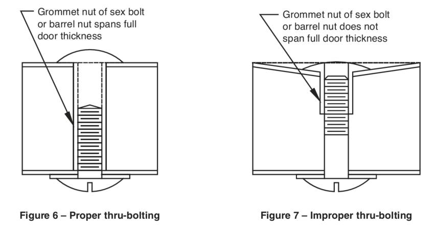
Important Note: Use only the correct size drill for pilot holes, as recommended by Machinery’s Handbook (see table 4). Larger holes will decrease screw holding power causing the screw to be pulled from the reinforcing under normal stresses (see figures 4 and 5).
Tables 2 and 3 illustrate the effect of variances in pilot hole sizes on thread holding power.
Table 2 – #10-24 thread
| Drill Size | Drill Diameter | % Full Thread |
|---|---|---|
| #23 | 0.154″ | 66% |
| #24 | 0.152″ | 70% |
| #25 | 0.149″ | 75% |
| #26 | 0.147″ | 79% |
| #27 | 0.144″ | 85% |
| “Machinery’s Handbook” recommendation in BOLD | ||
Table 3 – #12-24 thread
| Drill Size | Drill Diameter | % Full Thread |
|---|---|---|
| #15 | 0.180″ | 66% |
| #16 | 0.177″ | 70% |
| #17 | 0.173″ | 75% |
| “Machinery’s Handbook” recommendation in BOLD | ||
4.2.2 — The installer shall assure that tapped holes have 75% of full thread (considered a normal condition). This percentage shall not fall below 65% to be considered adequate for proper hardware fastenings. Drills shall be positioned so the bit enters the reinforced area in perpendicular position as holes formed at angles will not permit proper seating of the screw head. After the proper pilot holes are drilled, proceed with the tapping operation. The tap shall match the thread size of the screws provided and the tap shall be held perpendicular to the surface.
4.3 Thru-Bolting
Where reinforcing has not been specified or provided for other than mortised hardware, attachment shall be accomplished by thru-bolting. The hardware manufacturer’s instruction sheets shall be closely followed for recommended procedures. Where thru-bolting is required on hollow metal doors, spacers or sex-bolts shall be used to prevent collapsing of face sheets as illustrated in figures 6 and 7.
Note: The most popular thru-bolting applications are door closers, exit devices, overhead holders, pulls and bar sets.
4.4 Sheet Metal Screws
Sheet metal screws are normally used to attach accessory hardware such as kickplates, mail slots, room numbers, identification signs, and in many instances, push or pull plates. These areas are not reinforced beyond the thickness of the face sheets. Properly sized holes and correct sheet metal screws as provided with the hardware item or as specified in the mounting instructions shall be used for hardware attachment.
4.4.1 — The best performance is achieved when the space between the threads is equal to or greater than the thickness of the face sheets.
Table 4 – Tap drills and clearance drills for machine screws with American National Thread form
| Size of Screw | No. of Threads per Inch | Tap Drills | Clearance Hole Drills | |||||
|---|---|---|---|---|---|---|---|---|
| No. or Diam. | Decimal Equiv. | Drill Size | Decimal Equiv. | Close Fit | Close Fit | |||
| Drill Size | Decimal Equiv. | Drill Size | Decimal Equiv. | |||||
| 0 | .060 | 80 | 3/64 | .0469 | 52 | .0635 | 50 | .0700 |
| 1 | .073 | 64 72 | 53 53 | .0595 .0595 | 48 | .0760 | 46 | .0810 |
| 2 | .086 | 56 64 | 50 50 | .0700 .0700 | 43 | .0890 | 41 | .0960 |
| 3 | .099 | 48 56 | 47 45 | .0785 .0820 | 37 | .1040 | 35 | .1100 |
| 4 | .112 | 36* 40 48 | 44 43 42 | .0860 .0890 .0935 | 32 | .1160 | 30 | .1285 |
| 5 | .125 | 40 44 | 38 37 | .1015 .1040 | 30 | .1285 | 29 | .1360 |
| 6 | .138 | 32 40 | 36 33 | .1065 .1130 | 27 | .1440 | 25 | .1495 |
| 8 | .164 | 32 36 | 29 29 | .1360 .1360 | 18 | .1695 | 16 | .1770 |
| 10 | .190 | 24 32 | 25 21 | .1495 .1590 | 9 | .1960 | 7 | .2010 |
| 12 | .216 | 24 28 | 16 14 | .1770 .1820 | 2 | .2210 | 1 | .2280 |
| 14 | .242 | 20* 24* | 10 7 | .1935 .2010 | D | .2460 | F | .2570 |
| 1/4 | .250 | 20 28 | 7 3 | .2010 .2130 | F | .2570 | H | .2660 |
| 5/16 | .3125 | 18 24 | F I | .2570 .2720 | P | .3230 | Q | .3320 |
| 3/8 | .375 | 16 24 | 5/16 Q | .3125 .3320 | W | .3860 | X | .3970 |
| 7/16 | .4375 | 14 20 | U 25/64 | .3680 .3906 | 29/64 | .4531 | 15/32 | 4687 |
| 1/2 | .500 | 13 20 | 27/64 29/64 | .4219 .4531 | 33/64 | .5156 | 17/32 | .5312 |
* Screws marked with asterisk (*) are not in the American Standard but are from the former ASME Standard.
5. Continuous Hinges
5.1 — Standard preparation for continuous gear type or barrel type hinges shall not include any factory reinforcing, drilling and/or tapping in doors or frames. All mounting shall be prepared in the field by the hardware installer.
5.2 — For continuous hinges that require reinforcing (either for fasteners, door weight, door size or frequency of use situations) reinforcing shall be indicated at the time of order.
5.2.1 — Standard reinforcing shall be a 0.067″ (1.7 mm) steel strip no less than 1-1/4″ (31.7 mm) in width securely welded inside the hinge edge of doors and hinge jamb door rabbet of frames.
5.2.2 — Optional reinforcing shall be a 0.067″ (1.7 mm) steel strip no less than 1-1/4″ (31.7 mm) in width securely welded inside the hinge jamb door side face of frames.
5.3 — The hardware installer shall carefully follow the hinge manufacturer’s instructions for fastener preparations.
Appendix A
(informative)
Conclusion
It has been the experience of the Steel Door Institute that most failures of hardware attachments have been caused by improper field installation rather than insufficient reinforcement. It is quite obvious that it is easier to tap an oversize pilot hole than to tap one of correct size necessary for maximum strength. Oversized holes will not ensure adequate product performance.
Manufacturing tolerances and dimensions may not always be consistent on machine and sheet metal screws when compared with different sources of supply.
The material used for the manufacture of screws is also a factor in the overall performance of the attachment. Stainless steel, for example, is a stronger fastener than aluminum or plain carbon steel. On installations where vibration or unusual frequency of operation is a factor, the use of thread locking inserts, liquids on threads, or binding heads should be considered.
Standard steel doors and top grade builders hardware are made to provide many years of service and are very compatible. The specification writer and construction superintendent must be aware, however, that proper installation methods must be considered on an equal basis with door and hardware construction requirements to achieve this compatibility on the job.
Appendix B
(informative)
Bibliography
- HMMA 803 Steel Tables
- HMMA 830 Hardware Selection for Hollow Metal Doors and Frames
- HMMA 840 Guide Specification for Installation and Storage of Hollow Metal Doors and Frames
- SDI-117 Manufacturing Tolerances for Standard Steel Doors and Frames
- SDI-122 Installation Troubleshooting Guide for Standard Steel Doors and Frames
- SDI-134 Glossary of Terms for Standard Steel Doors and Frames