Installation Troubleshooting Guide for Standard Steel Doors and Frames
SDI 122-21
View PDF
Table of Contents
- Foreword
- Purpose
- Improper Door/Frame Clearance
- Door Bind Against Rabbet
- Hinge Bind Against Stops
- Twisted Door
- Twisted Door Adjustments
- Twisted Frame
- Frame Set out of Square
- Frame with Rabbets Toed In or Out
- Silencers
- Lock Fits Loose on Strike
- Lock Fits Too Tight in Strike
- Lockset Off Location on Door Strike Off Location in Frame in Wall
- Miter Not Closed on Frame
- Clearance at Bottom of Door Too Small
- Frame and Door Hinge Misalignment
- Frame Loose on Drywall
- Glazed Window Units
- Label Missing from Fire-Rated Frame
- Label Missing from Fire-Rated Door
- Paint Problems
- Water Stain Damage
- Thermal Bow
1. Foreword
The material contained in this document has been developed under the auspices of the Technical Committee of the Steel Door Institute.
The Steel Door Institute does not condone or encourage repair methods which would adversely affect product performance or violate and/or void product warranties.
The user of this document assumes all responsibility associated with but not limited to product performance and violation of product warranties for any product associated with the installation and suggested repair methods in this document.
2. Purpose
The intent of this document is to cover field installation problems most commonly experienced with standard steel door and frame installations. It should be understood that most problems encountered are because of inappropriate application of the products and/or improper installation.
The suggested method of repairs requires only basic hand tools and relatively little time. It should be understood that more complex problems or compound problems could exist which warrant extensive field repairs and modification to products. These types of field installation problems are not intended to be covered in this document and should not be made without first consulting the manufacturer.
Modifications made to fire-rated-labeled doors and frames shall be made in compliance with NFPA 80.
3. Improper Door/Frame Clearance
To ensure proper door and frame function, the clearance between the door and frame must be properly maintained. All standard steel door and frame manufacturers closely hold tolerances that result in a nominal clearance between the door and frame of 1/8 inch. If this clearance is not maintained, interference and hardware misalignment may occur.
Proper installation is extremely important in establishing clearances and preventing a multitude of potential problems.
The Steel Door Institute has many publications which were developed to establish industry standards and assist in specifying as well as installing standard steel doors and frames. One publication, ANSI/SDI 250.11, Recommended Erection Instructions for Steel Frames, will be of assistance regarding the erection and installation of standard steel frames.
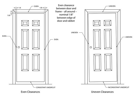
| Is door sagging? Uneven clearances frequently result from improper installation of frames and frame anchors. The condition, characterized by lock edge clearances narrow at the top and wide at the bottom, is called “door sag”. The following suggested adjustments may correct the condition. | 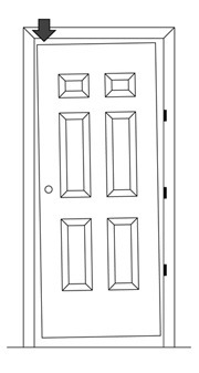 |
| Are hinges loose? Are hinges worn? | 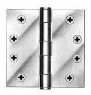 |
| Are hinges properly swaged? Swaging is a slight offset of the hinge leaf at the barrel which permits the leaves to come together. | 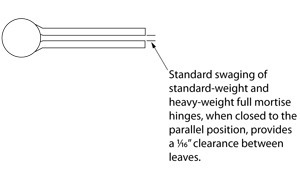 |
| Remove top hinge filler for non-handed doors The improper clearance condition may be improved by removing the top hinge leaf attached to the door and taking out the filler (hinge filler) from behind the leaf. Once completed, reattach hinge leaf to door. A hinge filler is used on all non-handed doors. | 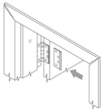 |
| Add shims to bottom and/or middle hinge On handed or non-handed doors, the lower half of the door can be shifted upward and toward the strike jamb. Remove the screws which attach the middle and/or bottom hinge(s) to the door. Insert shims between the hinge leaf and door. Reattach hinge leaf to door. | 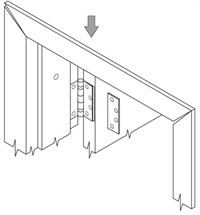 |
Standard-weight to heavy-weight hinge modifications
Although styles and types vary, many manufacturers offer built-in features that allow hinge pockets on doors and frames to be modified from standard-weight to heavy-weight. Examples of the different methods are: grinding or flattening down raised embossments in shim plates or reinforcements; removing or breaking off hinge filler shim plates; adjusting set screws; and removing wire shims. These options all involve removing material from the pocket to allow for heavy-weight depth to be achieved. As always, check with individual manufacturers to determine the type of modifications offered.
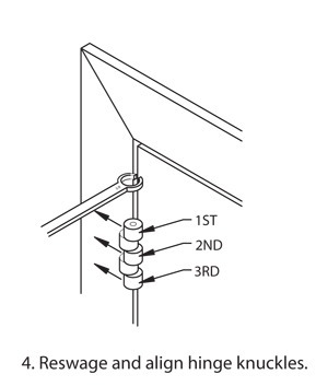
| Reswaging hinges The following example shows how a hinge leaf can be reswaged to correct minor improper door/frame clearances. This particular method allows the reswaging to be accomplished while the door remains in the opening and the hinge leaves remain on the door and frame. The example shows a top hinge reswaged to correct a sag-type condition. However, any of the hinges can be reswaged in this manner to compensate for conditions opposite to that of a sag condition. |
|
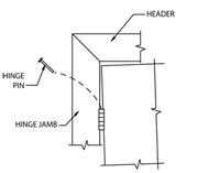
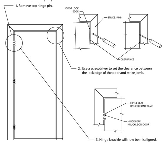
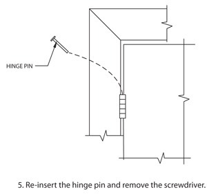
| As shown, the hinge leaf knuckles on the door move to a new location once the clearance at the strike jamb is set. The hinge leaf knuckles on the frame must now be reswaged (bent) to align with the new location of the hinge leaf knuckles on the door. The simplest way to do this is to use a 5/8” – 11/16” tube wrench (a crescent wrench will do as a second choice). Simply slip the tube wrench down around the 1st knuckle and align it with the new location. Once the first knuckle has been aligned, the wrench will now slip down to the 2nd knuckle for alignment. Repeat the process on the third knuckle.
|
|
Is the door binding?
Frames which are out of plumb will likely cause improper operation of locksets and binding of bolts in the strike. Check carefully the installation of the frame prior to making hardware adjustments.
4. Door Bind, Against Rabbet
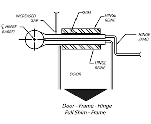
Normally, hinge bind is found between the door and rabbet. There are several ways of shimming which will move the door in different directions. The following guidelines should be used in shim applications.
| 2.1 This method will move the door toward the Strike jamb. It will leave a small gap between Hinge and Frame face. It will not prevent or help hinge bind. |
|
| 2.2 This method will move the door toward the Strike jamb. It will leave a small gap between Hinge and Door face. It will not prevent or help hinge bind. | 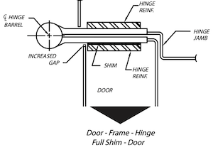 |
| 2.3 This method will move the door toward the Strike jamb. It will leave a small gap between Hinge and Door and Frame face. It will not prevent or help hinge bind. | 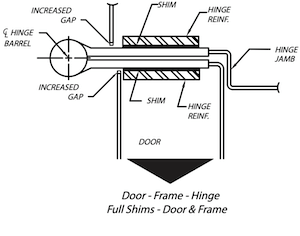 |
5. Hinge Bind, Against Stops
Hinge bind against the frame stops is possible field condition. Again, there are several ways of shimming which will move the door in the desired direction. The following guideline should be used in shim application.
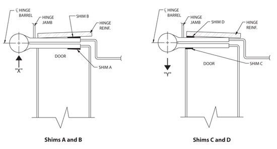
Adjustment of Clearance Between the Door and the Frame May be Accomplished by the Following:
- Using Shim “A” only, door will be relocated in direction of Arrow “X”.
- Using Shim “B” only, will move both door and centerline of hinge barrel in direction of Arrow “X”.
- Using both Shims “A” and “B” will relocate the door in direction of Arrow “X” by a greater amount than by using Shim “B” alone.
- Using Shim “C” only, door will be relocated in direction of Arrow “Y”.
- Using Shim “D” only, both door and centerline of hinge barrel will move in direction of Arrow “Y”.
- Using both Shims “C” and “D” will relocate the door in direction of Arrow “Y” by a greater amount than by using either “C” or “D” alone. The centerline of hinge barrel will be relocated the same as by using Shim “D” alone.
6. Twisted Door
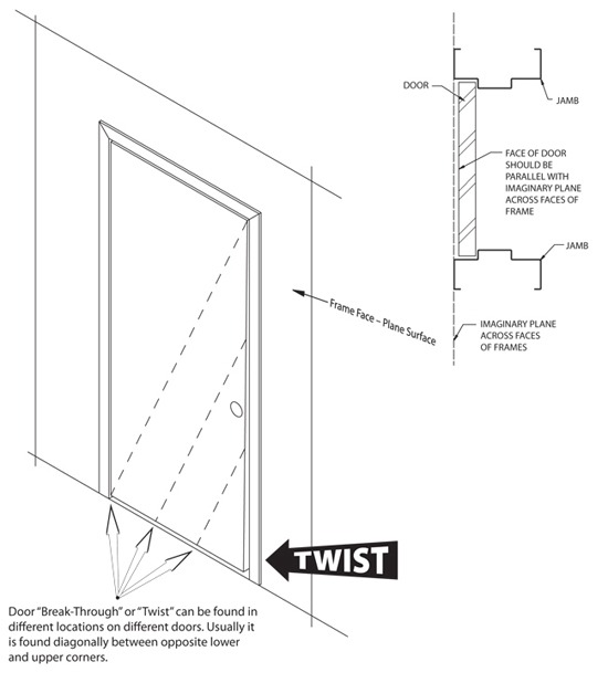
Normal installation results in the plane of the door face being parallel with the plane of the frame face. If the frame is square and plumb, all face surfaces of the frame will be in the same plane. A twisted door will “break through” the frame’s face plane surface. BE SURE the frame is square and plumb. If it is not, the problem is probably with the frame installation and NOT the door.
7. Twisted Door Adjustments
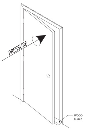
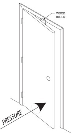
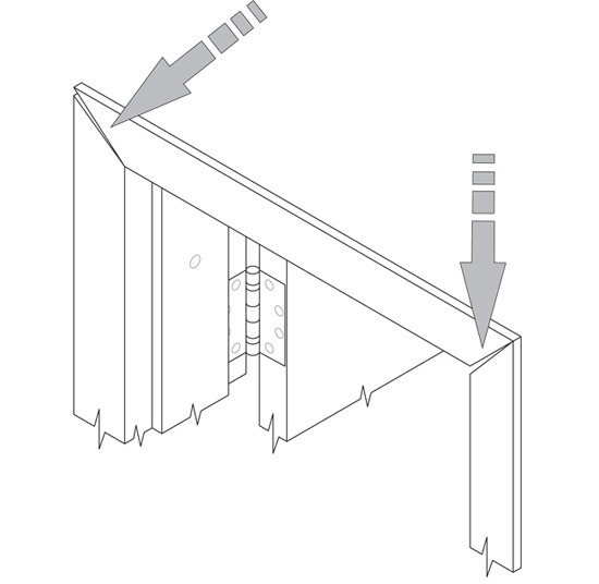
When required, it is possible to “spring” the door back to (or much closer to) its ideal position of being parallel with the imaginary plane across the faces of the frame. This can usually be done with the door remaining in the frame. A piece of wood blocking must be placed between the door and frame. Pressure is then applied at the twisted area to “spring” the door. However, caution should be exercised on drywall installations since the frame could possibly work lose from the wall, particularly with slip-on drywall type frames.
| Twisted at Top When the top lock area of a door is “breaking-through” the imaginary plane, place a wood block on floor, between door and frame as shown. Apply pressure to the top lock area as shown to “spring” door back into position. Remove wood block, close door and check condition. Repeat if necessary. |
 |
| Twisted at Bottom When the bottom lock area of door is “breaking-through” the plane, place a wood block between frame head and door as shown. Apply pressure to the bottom lock area as shown to “spring” door back into position. Remove wood, close door and check condition. Repeat if necessary. |
 |
An alternate method can also be used which will allow the door to remain in the opening. This method might be appropriate in drywall installations as previously mentioned. Although the example shown deflects the top half of the door, this method could be used on the bottom half of the door as well.
8. Twisted Frame
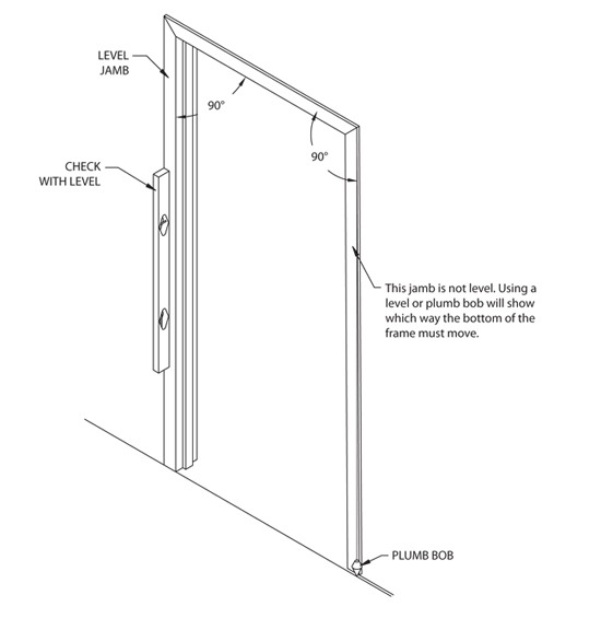
Wall conditions and anchoring methods can cause the frame to be “twisted” in the opening. The two jamb (hinge and strike) faces are not in the same plane as discussed in the twisted door section. This can be checked by using a level and/or plumb bob. Frames do not have adjustments when it comes to “twist”.
The “twist” condition is generally caused by the wall conditions. The frame jamb faces are prevented from being set in the same plane because the walls are out of plane to begin with.
The options available to correct this problem depend, to a large extent, on the wall construction.
9. Frame Set Out of Square
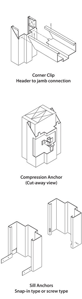
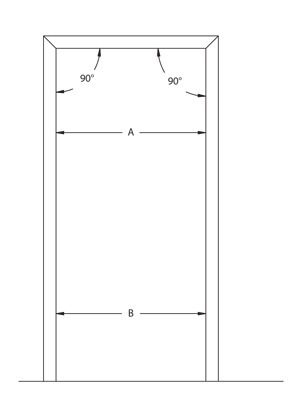
| Proper frame installation cannot be overemphasized. In the majority of wall constructions, (“slip-on” drywall type frames being the major exception) “quick” or “easy” field fixes are limited. Improperly set frames that are drastically out of square will cause severe door and hardware problems. These types of situations would require extensive field repair and may result in having to remove frames from walls. If the “out of square” condition is slight, some adjustment can be made by shimming and/or adjusting anchors, particularly if the frame being worked on is a slip-on drywall type. The most versatile frame to work with in correcting these types of conditions is the “slip-on” drywall frame. The manufacturers’ instructions should be referenced, but generally most “slip-on” drywall frames have a sill anchor at the bottom of the jamb and a compression anchor between the top hinge and the header. Also, most jambs have corner clips that have a hole to accept a screw. The corner clip and hole align with a hole in the header. The adjustment of slip-on drywall frames can be made using these anchors or corner clips. PROPERLY SET FRAME |
|
The following examples illustrate how a frame can be set out of square.
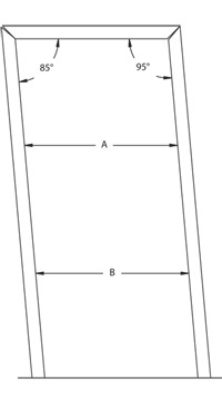 | IMPROPERLY SET FRAME (A) One corner is greater than 90º and one corner is less than 90º. The miters do not properly align with one another and “gaps” are created in the miters which are opposites of one another. The dimension taken at point “A” would remain the same when checked at point “B” if the 90º corners are out of square an equal number of degrees. This condition can be corrected by adjusting the compression anchors in and/or out of each jamb as required. Loosen the corner clip screws if the frame is so equipped before making adjustments; retighten when finished. The compression anchors must be adjusted (turned) in opposite directions to allow the jambs to move. For the illustration shown, the strike jamb compression anchor screw must be turned counterclockwise to retract the compression anchor and give room for the frame to be adjusted back into position using the hinge jamb compression anchor. The hinge jamb compression anchor screw is then turned clockwise to advance the anchor and push the frame towards the room made at the strike jamb. The frame should be brought into square with the header and the hinge jamb compression anchor. Once this is done, the strike jamb compression anchor screw can be turned clockwise, advancing the anchor snug against the stud. The corner slip screws should then be retightened. |
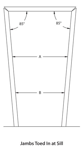
| IMPROPERLY SET FRAME (B) The corners are both greater than or less than 90º. The miters do not properly align with one another. When the corner is less than 90º the miter will have a gap which increases as it goes towards the return. When the corner is greater than 90º the miter will have a gap, which increases as it goes towards the rabbet. Dimensions taken at point “A” and “B” will not be equal. This condition will always result in dimension “B” being either greater than or less than the nominal opening dimension which would be obtained if checked between jambs along the header. |
|
| To correct this condition, the sill anchors must be loosened to allow the bottom of each jamb to be moved in and/or out. In the case of the snap-in type sill anchor, the baseboard trim might have to be removed to gain access to the anchors. This type of anchor is generally used because it can be hidden by covering it with the baseboard trim. If the jambs are toed in at the sills, the compression anchors might have to be retracted slightly so the sill (base) of the jambs can be pushed out. The jambs should be plumbed, squared with the header and leveled as they are pushed out into their proper position. The sill anchors should be reset, the compression anchors adjusted and retightened. The baseboard trim should be reattached to the wall if it had been removed. A similar procedure should be used if the jambs are toed out at the sills. The sill (base) of the jambs should be pushed in towards the opening. The jambs should be plumbed, squared with the header and leveled as they are pushed into their proper position. The sill anchors should be reset, the compression anchors adjusted (extended) and retightened. The baseboard trim should be reattached to the wall if it had been removed. | 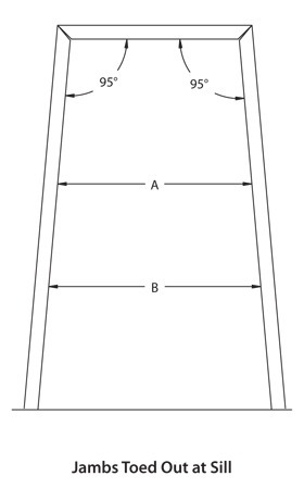 |
| IMPROROPERLY SET FRAME (C) One corner is properly set at 90º while the other corner is greater or less than 90º. The dimension taken at point “A” will constantly change when checked at various points going towards point “B.” The corner miter will not properly align between the header and jamb which is not set at 90º. The jamb which is not 90º to the header must be moved. To correct this condition, the sill anchor must be loosened to allow the bottom of the jamb to be moved in or out as required. In the case of the snap-in type sill anchor, the baseboard trim may have to be removed to gain access to the anchor. This type of anchor is generally used because it can be hidden by covering it with the baseboard trim. | 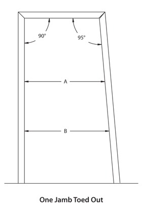 |
| If the jamb is toed in at the sill, the compression anchor may have to be retracted slightly so the sill (base) of the jamb can be pushed out. The jamb should be plumbed, squared with the header and leveled as it is being pushed out into its proper position. The sill anchor should be reset, the compression anchor adjusted and retightened. The baseboard trim should be reattached to the wall if it had been removed. A similar procedure should be used when the jamb is toed out at the sill. The sill (base) of the jamb should be pushed in towards the opening. The jamb should be plumbed, squared with the header and leveled as it is pushed into its proper position. The sill anchor should be reset, the compression anchor adjusted (fastened) and retightened. The baseboard trim should be reattached to the wall if it had been removed. | 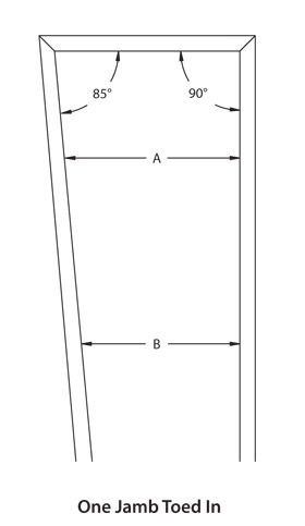 |
10. Frame with Rabbets Toed In or Out
The importance of proper initial frame installation is evident in this condition. In the majority of wall constructions, except for the “slip-on” drywall type frames, “quick,” “easy” field fixes are limited. Improperly set frames which have the rabbets drastically toed in or out would require extensive field repair and in most cases require that the wall be entered to gain access to frame anchoring.
The toed in or out condition is worse near the floor. The header prevents the upper portion of the jambs from toeing in or out but as you move away from the header towards the floor, the jambs have greater potential to be toed in our out during installation.
The only frame with this condition which can be corrected with little difficulty is the “slip-on” drywall frame. Since the “slip-on” drywall frame uses only compression anchors near the head and sill anchors near the bottom of the jambs, this condition is easily corrected.
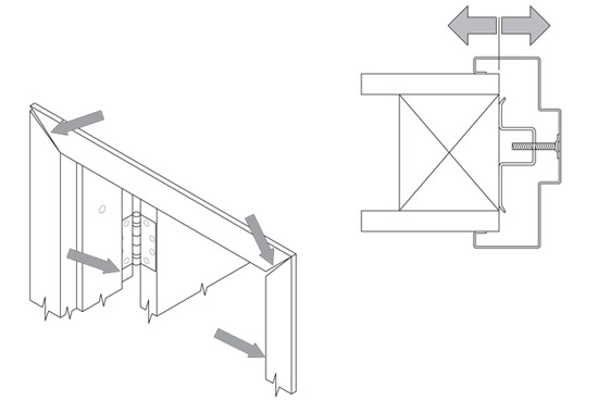
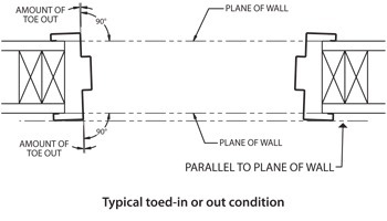
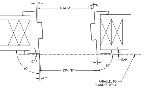
| Note that the rabbet surfaces are not 90° to the plane of the wall. This can be checked by placing a straight edge across the face of both jambs. The straight edge should set flat across both faces at the same time. If the jambs are twisted, a “gap” will be created as shown in the figure to the left. |
|
| The figures to the right show the two typical types of sill anchors used on the “slip-on” drywall frame. “A” shows an anchor which will be covered up by the baseboard trim. To gain access to this anchor the baseboard trim must first be removed. Next, the nails or screws holding the anchors to the wall must be removed. This will loosen the jamb and allow it to be squared in the opening. “B” illustrates a screw going through the face of the frame into the wall. This holds the sill of the frame in position. This screw is exposed and is readily accessible. Removing the screw will loosen the jamb and allow it to be “squared-up” in the opening. If both jambs are toed in/out, they both should be “squared-up.” This can be checked by taking measurements as shown below. Both the “A” and “B” dimensions will be the same when the frames are properly set. However, the frame jambs must be plumb, level, and square with the head of the frame. | 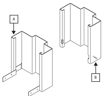 |
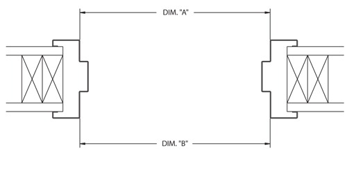
If both jambs are toed in/out, they both should be “squared-up.” This can be checked by taking measurements as shown above. Both the “A” and “B” dimensions will be the same when the frames are properly set.
The below figure shows a condition which can give the impression that the frame is properly installed. Both dimensions “A” and “B” will be equal but the frame will not be square in the opening. Both jambs can be twisted to create a parallelogram. This can be checked by placing a straight edge across the face of both jambs (the straight edge is represented by the dotted line shown below. The straight edge should set flat across both faces at the same time. If the jambs are twisted, a “gap” will be created as shown in the illustration. The “gaps” will be to the same side if a parallelogram was created. The gaps could also be to opposite sides as shown in the Typical Toed In or Out Condition figure on the previous page.
This condition can be corrected as outlined for the other “toe out” or “toe in” examples.
11. Silencers
Some manufacturers provide a silencer hole in the frame stop to accept a push-in silencer. A “stick-on” silencer is also available for application to frames without the silencer hole. The silencer acts as a “rubber bumper” which evenly holds the door off the stop at a constant distance. If the door is held off of the stop rather than being allowed to move slightly towards the stop, the latch tube will fit tighter into the strike. Three silencers are placed on the strike jamb, one toward the top of the jamb (nearer the header) and one toward the bottom of the jamb (nearer the sill) and the third near the strike preparation.
12. Lock Fits Loose on Strike
This condition cannot be caused by an improperly set door and/or frame. If the lockset on the door was not properly aligned with the strike on the frame, interference would occur or the latch bolt would bind in the strike. Since this is not the case; the cause is something other than improper installation. The following should be checked:
PROPER STRIKE
Is the proper strike plate attached to the frame?
RIM EXIT DEVICES
An adjustable strike plate is provided. Is the strike plate properly adjusted to prove positive and secure latching?
13-Lock Fits Too Tight in Strike
Proper installation of the door and frame are essential. If the door and frame are not properly aligned, the latch bolt could bind in the strike. The following items should be checked:
IMPROPER CLEARANCE/DOOR SAG
For various conditions, click here.
HINGE BIND
For various conditions of hinge bind, click here.
TWISTED DOOR
For various conditions of twisted doors, click here.
TWISTED FRAMES
For various conditions of twisted frames, click here.
FRAME SET OUT OF SQUARE
For various conditions of frames set out of square, click here.
PROPER STRIKE
Is the proper strike plate attached to the frame?
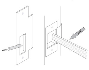
The previously mentioned items should be checked and any problems corrected. If the latch continues to tightly engage the strike, additional clearance can be created by filing the strike or bending the latch bolt lip as shown. However, this should only be done as a final option.
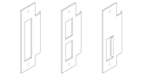
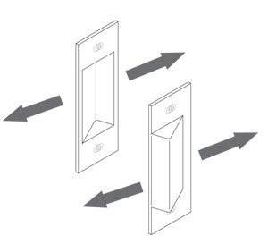
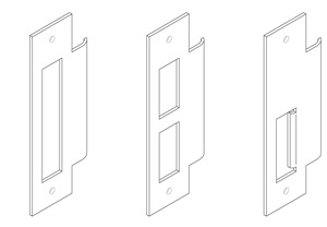
14. Lockset Off Location on Door or Strike Off Location in Frame Wall
Minor location adjustments usually can be accomplished by altering the strike plate. The strike plate alteration would “extend” the opening to allow the latch tube to properly engage the strike. This is similar to the section “Lock Fits Too Tight in Strike” except that the amount of material removed from the strike is greater. This could compensate for minor mislocation of the strike plate on the frame and/or location of the lockset on the door. These general steps should be followed for modifying the strike plate.
| 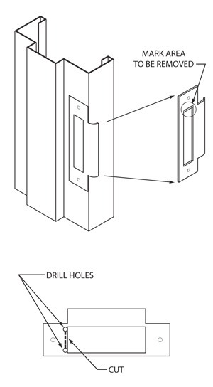 |
15. Miter Not Closed on Frame
The major cause of miters not properly lining up and “closing” is incorrect installation. The effects of improper installation on miter seams are covered under the previous section of “Frame Set Out of Square.” This section should be referenced for detailed explanations of conditions which could occur, and solutions for correcting the problems.
This condition could also be caused by conditions as explained in the Frame Loose on Drywall Section.
16. Clearanace at Bottom of Door Too Small
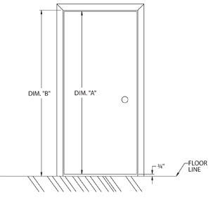
The available options for correcting this problem are limited. Frames which are permanently anchored to the wall construction (such as masonry or steel stud) leave few alternatives. The only available “fix” is to trim the bottom of the door, if the door’s construction will permit trimming. As shown in the figure below, the nominal “sill clearance” should be ¾ of an inch. The sill clearance is the dimension from the bottom of the door to the bottom of the frame jambs, and ¾” is a standard industry wide dimension.
The frame jambs should be set at floor level which then results in ¾ of an inch between the bottom of the door and floor.
The ¾“ also provides enough room to allow the installation of a “raised sill” which is a type of flat threshold. If a raised sill is used, the ¾ inch clearance is decreased.
Before any alterations are made the door height dimensions should be checked.
The door height is determined by taking a measurement represented by dimension “A” in the figure. If the door height is “oversize” the clearance at the bottom will be too small.
The frame jamb height (which is the same as the opening height) is determined by taking a measurement represented by dimension “B”. If the jamb height is “undersize,” the clearance at the bottom will be too small.
The bottom of the frame jambs should be set “on” the floor not “in” the floor. In some special cases the jambs can be set “in” the floor but this requires special design consideration and adjustments in door height and jamb heights. If this was not compensated for in the designed heights, the clearance at the bottom could be too small.
By taking these basic dimensions, you can confirm what element of the opening is in error. If trimming the bottom of the door is considered, you must make sure that the door’s design will allow such a modification to be made. It is best to contact the distributor or the manufacturer to determine if and how much the door can be trimmed. These types of trimming modifications can be relatively simple or more extensive depending on door design.
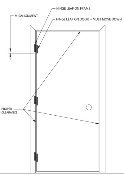
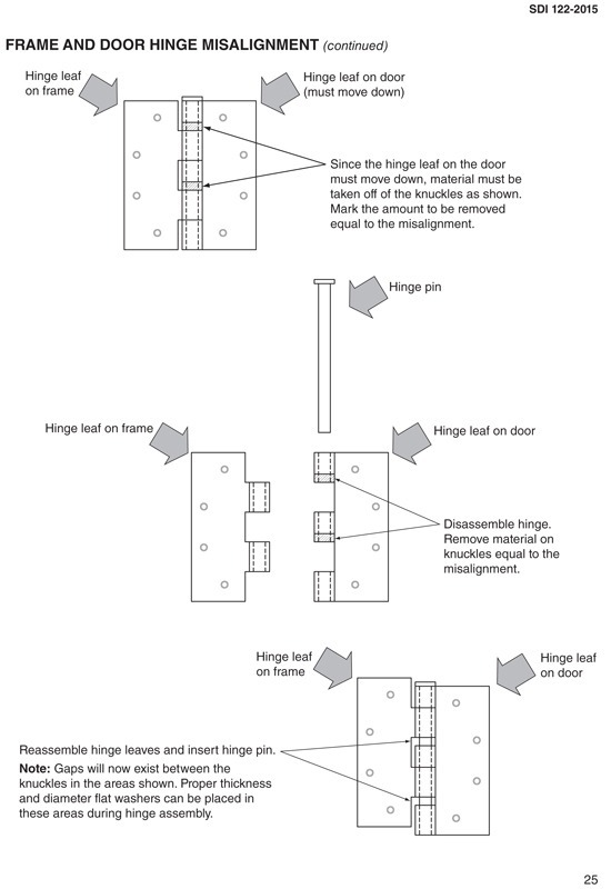
17. Frame and Door Hinge Misalingment
Frame and door hinge misalignment can cause a variety of problems. When misalignment occurs, either the door’s hinge locations or frame’s hinge locations are slightly off. This can apply to retrofitting existing openings where either the door or frame is being replaced, but not both. When new doors and frames are provided from a single manufacturer, this problem does not exist.
The example shown on the following page reflects the dropping of the hinge leaf which attaches to the door from its relationship to the hinge leaf on the frame. However, by removing material from the opposite end of the knuckles, the door hinge leaf could be raised as well. The frame hinge leaf can also be relocated in similar fashion.
18. Frame Loose on Drywall
Frame manufacturers closely control the dimensions to which their frames are manufactured. Since automated equipment is used these dimensions are easily repeated from piece to piece. The majority of cases where frames are loose on drywall will reveal that the overall wall thickness has not been properly maintained. Wall thickness conditions can vary from undersize to oversize. The thickness should be checked, if possible, to verify the wall’s compliance with the job specification.
Frames installed in drywall walls can use two different anchoring methods:
WELDED/SNAP-IN STEEL OR WOOD STUD ANCHORS
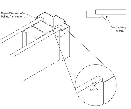
Some frames use welded or snapped-in steel or wood stud anchors. These frames are installed prior to the drywall material being attached to the studs. The drywall can either be “butted-up” against the return of the frame or be “tucked in” behind the return of the frame. Only in the installation where the drywall is “tucked in” behind the return can there be a condition where the frame is loose on the drywall. This gap could be uniform along the entire length (height) of the jamb or could be only in certain areas. Since the frame cannot be removed, the only available options are to caulk the gap or cover it with trim.
DRYWALL FRAMES WITH COMPRESSION ANCHORS
These frames are intended to be installed after the wall construction is complete. The anchoring methods that this type of frame uses allows the removal of the frame if so desired. The manufacturers’ installation instructions should be followed anytime the frame is removed and reinstalled. Three conditions could exist for drywall slip-on frames which are “loose on the wall.”
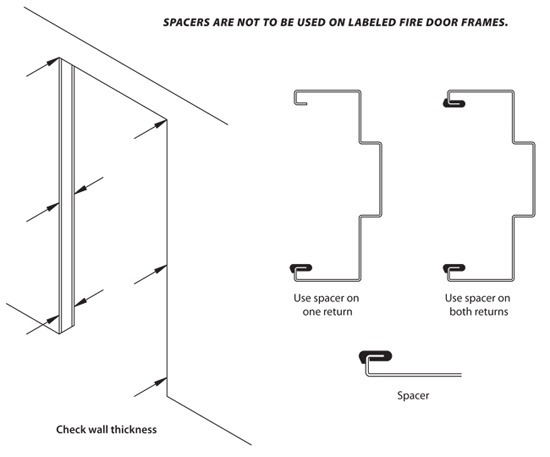
1) The first condition is a uniform gap along the entire length (height) of the frame jambs. The frame should be removed from the opening and the wall thickness checked at numerous places around the opening. These measurements should be compared to the job specifications. If the wall thickness is undersize, two options are available.
a) If the gap is relatively small, the use of caulking or trim can be considered to cover the gap when the frame is installed.
b) If the gap is larger, the use of “spacers” can offset the lacking wall thickness. The use of spacers requires that the frame be removed from the opening, the spacer(s) attached, and the frame reinstalled. The spacers can be used on either one or both of the frame returns which would result in spacers on either one side or both sides of the wall. Spacers are available from the frame manufacturer.
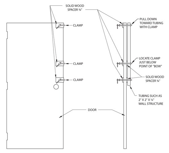
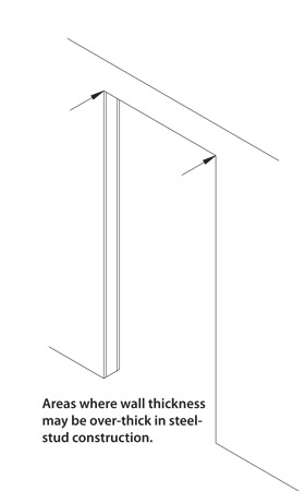
2) The second condition would be a gap that changes along the length (height) of the jamb. This condition is generally found in steel stud construction and results in “over thick” walls in the upper corners of the opening, refer to Figure 5. This is usually a direct result of how the steel stud headers were attached to the vertical steel studs to form the opening. When the wall is oversize (in this area) it will force the header and jamb miters to spread apart and actually open up the throat dimensions to accept the oversize wall. This will cause the corners of the frame to be extremely tight on the wall and as you progress down the jamb, a gap will begin to develop and then gradually disappear closer to the floor, see figure further below on “Gap produced by oversized wall”.

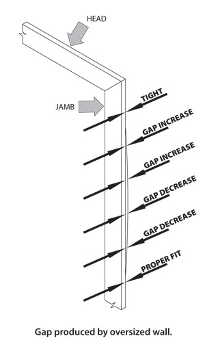
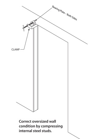
This condition should be reported to the appropriate jobsite personnel. The condition can be corrected by putting a bearing plate on each side of the corner and compressing the internal steel studs with a clamp. However, the responsibility for correcting this condition belongs to the sub-contractor responsible for the actual wall construction.
3) The third condition is different from the first two which address the “fit” of the frame over the wall thickness. The cause of this condition is compression anchors which have not been tightened. The drywall frame would then be loose across the width of the opening and move from side to side against the rough opening.
The frame should be plumbed, squared and secured in the opening by properly adjusting the compression anchors following the manufacturers’ instructions.
19. Glazed Window Units
Hollow metal borrowed light, transom, and combination sidelight frames are an excellent choice for exterior openings due to their design flexibility, thermal performance, and security. These types of frames are not factory sealed to prevent water infiltration; the contractor/installer must seal all joints that are exposed to the elements after the frame assembly is installed.
Whenever possible it is strongly recommended that the glass and glazing be installed on the exterior rabbet of the frame. This will act as a deterrent to water penetration.
Manufacturers cannot control the workmanship associated with the installation of these types of frames, therefore, this work must be specified in the installation/glazing/caulking section of specifications.
20. Label Missing from Fire-Rated Frame
Like doors, fire-rated frames are an important element of compliance with building codes and fire protection standards. Consequently, proper control of the labels which are attached to the frame is top priority for the manufacturer, code official and labeling agency. Once the product is in the field, whether it is installed or not, no one, including the manufacturer is permitted to attach labels unless a representative of the manufacturer’s labeling agency has inspected the product for compliance with the manufacturer’s procedures. Only authorized individuals can be in possession of and attach labels to fire rated products in the field.
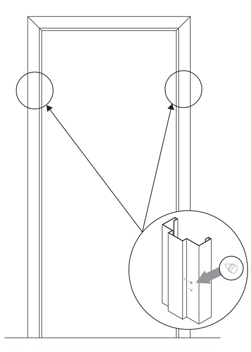
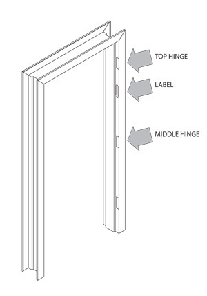
All labels on fire rated frames are located on the hinge jamb between the top and middle hinge (see figure below). It should be noted that some frames have an embossed label, rather than a surface-attached label. The embossed label is stamped into the frame rabbet and can be painted over.
If the label or embossment is not present, the frame distributor should be contacted.
| Special Notes:
|  |
21. Label Missing from Fire-Rated Door
Fire-rated doors are an important element of compliance with building codes and fire protection standards. Consequently, proper control of the labels is top priority for the manufacturer, code official and labeling agency. (The manufacturer must account for every label used and the label can only be applied at the manufacturer’s facility or at an authorized labeling distributor of the manufacturer.) Once the product is in the field, whether it’s installed or not, no one, including the manufacturer is permitted to attach labels unless a representative of the manufacturer’s labeling agency has inspected the product for compliance with the manufacturer’s labeling procedures. Only authorized individuals may be in possession of and attach labels to fire rated products in the field.
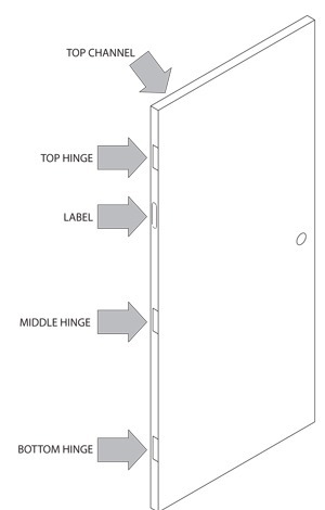
Labels on fire-rated doors are located in one of two places, either between the top and middle hinge, or on the top channel (see figure). Be sure you are looking for the label in the correct location.
If the label is not present, the door distributor should be contacted.
| Special Notes:
|  |
22. Paint Problems
PAINT PEELING TO BARE METAL
Two conditions exist that must be considered when evaluating paint peeling to bare metal.
1. PRIME PAINT ONLY
If the product is only prime painted, and peeling has occurred, then poor adhesion between the primer and bare metal has occurred. This can usually be attributed to inadequate surface preparation before prime painting. The bare metal must be adequately prepared to ensure good prime paint adhesion. The door should be completely sanded, washed with solvent and re-primed. The sanding and washing operations provide an adequate surface to assure good primer adhesion.
2. PRIME PAINT AND TOP (FINISH) COAT
The failure could be caused by either poor surface preparation before prime painting or the use of a non-compatible finish paint that has reacted with the primer and lifted all paint from bare metal. In either case the corrective measure would be the same. The door should be completely sanded and washed with an appropriate solvent. The door should then be re-primed. Lightly sand the prime coat, wipe and finish-paint with a compatible top coat. Whenever the door is being prepared for top or finish-coat painting the surface should be cleaned. Use the same solvent that will be used to thin the topcoat paint and thoroughly clean all surfaces to be painted.
PAINT IN TAPPED HOLES
Both hollow metal doors and frames have various holes that are drilled and tapped. These holes are in various components such as reinforcements. All of the components are brought together as an assembly prior to the painting operation.
There are a variety of painting methods manufacturers can use. Some of these methods can result in paint build-up in the tapped holes of the reinforcements. This build-up can make installation of screws difficult. The build-up should be removed to make screw installation easier and assure that the screws are properly seated.
The best method of cleaning the tapped holes is to use an actual thread tap which matches the screw thread. The tap will easily cut though and clean paint build-up and by running it in and out of the hole. If the build-up is not as great and extra screws are available (or can be obtained) a screw can be run in and out of the hole to clean minor build-up prior to final screw installation.
23. Water Stain Damage
Water stain damage is a direct result of improper storage. If the product is still in prime paint (no finish coat has been applied) the condition is easily detectable as follows:
- Initially, the water stain appears as a discoloration or variance in sheen or gloss in the primer. Damaged areas will look and possibly feel different from the rest of the product.
- If the water stain has existed for a considerable length of time and was caused by • large amounts of water, rust will start to appear through the discolored areas.
If the product has had a finish coat of paint applied, water stain damage can cause failure of the finish coat as well:
- Water stain damage can be detected by random areas of finish paint failure on the door as well as the appearance of uniform rust development on those areas. In some cases the finish paint will show good adhesion in water damaged areas but will also show a uniform layer of rust developing through the finish paint.
To correct water stain damage, use the following guidelines:
- For products that are prime painted only, the affected areas should be adequately • sanded. If necessary, the area should be sanded to bare metal. The entire door/frame surface should then be lightly sanded and “feathered” into any heavily sanded areas. The entire surface should then be re-prime painted.
- For products that are finish painted, the affected areas should be adequately sanded. • If necessary the area should be sanded to bare metal. The entire remaining finish-painted area should then be lightly sanded and “feathered” into any heavily sanded areas. If bare metal is showing, these areas should be re-prime painted and lightly sanded to “feather” into the lightly sanded finish-painted areas. The product should then be re-finish painted.
- When the door is being prepared for top or finish coat painting, the surface should first be cleaned. Use the same solvent that will be used to thin the topcoat paint and thoroughly clean all surfaces to be painted.
24. Thermal Bow
Installers need to be aware of a condition known as Thermal Bow. Thermal Bow is a temporary condition which may occur in metal doors due to the inside-outside temperature differential. This is more common when the direct rays of the sun are on a door surface. This condition is temporary, and to a great extent depends on the door color, door construction, length of exposure, temperature, etc. This condition can often be alleviated by painting the exposed surface a light color. Thermal bow can occur in reverse under extremely cold conditions. Typical symptoms of thermal bow are hardware latching difficulty and door clearance issues.