American National Standard
Test Procedure and Acceptance Criteria for Physical Endurance for Steel Doors, Frames and Frame Anchors
ANSI/SDI A250.4-2022
Revision of ANSI/SDI A250.4-2018
View PDF
Table of Contents
- Purpose
- Reference Document
- Disclaimers
- Apparatus and equipment
- Door opener
- Hardware
- Preparation for test
- Test specimen
- Doors
- Frames
- Swing test
- Doors
- Frames
- Twist test
- Acceptance criteria
- Doors
- Frames
Figures
Performance Reports
Annex
1. Purpose
The primary purpose of this procedure shall be to establish a standard method of testing the performance of a steel door mounted in a hollow metal or channel iron frame installed with appropriate anchors, under conditions that might reasonably be considered an accelerated field operating condition.
The user of this performance standard must temper their usage with the knowledge that there are many variables that affect door and frame performance, such as different hardware, anchors, glass and louver cutouts, field modification by parties other than the manufacturer, environmental factors, such as heat, cold, moisture, etc.
1.1 Reference Documents
- ANSI/BHMA A156.1-2013 revised to A156.1-2021 Butts and Hinges
- ANSI/BHMA A156.3-2014 revised to A156.3-2020 Exit Devices
- ANSI/BHMA A156.4-2013 revised to A156.4-2019 Door Controls — Closers
1.2 Disclaimers
1.2.1 Tolerances
All values which do not carry specific tolerances or are not market maximum or minimum shall have the following tolerances: Linear dimensions shall be +- 1/16 in. (1.6 mm), Weight or force shall be +- 2%. Angles shall be +- 2 degrees. Where only minus tolerances are given, the dimensions are permitted to be exceeded at the toption of the manufacturers.
1.2.2 Gauge vs. Thickness
While the term ‘gauge’ is no longer common for defining material thickness it is stillused to specify doors and frames for ordering purposes. The term ‘thickness’ is used when defining the actual dimension of an item, and th eterm ‘guage’ is used in the context of specifying a particular door or frame.
2. Apparatus and equipment
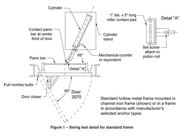
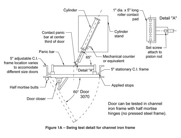
The apparatus and equipment used shall be the same when testing doors or frames with frame anchors. The main testing structure shall be constructed as shown in figures 1 and 2. The structure shall conform to the parts shown, except the opening width and height are permitted to vary to allow the testing of various door sizes. The test frame for testing doors or frames shall be anchored in such a manner as to ensure rigidity.
The swinging mechanism shall be in two parts:
2.1 Door opener
The door opener shall be an air cylinder positioned at 65° to the plane of the door in its closed and latched position that will actuate an exit device mounted on the test door. The contact point shall be set to push the door open 60° ± 5°, and retract to allow the door closer to bring the door back into its original closed position and then begin the cycle again. See the requirements in figures 1 and 1A.
2.2 Hardware
The exit device, door closer and hinges used in testing shall be selected based on the door manufacturer’s recommendations for the testing level described in Swing Test Form 1. The door manufacturers’ and model number shall be recorded in the report. All hardware shall be applied to the door and frame with fasteners provided by the hardware manufacturer (for example, machine screws or sex bolts) in the location recommended by the door manufacturer. The hardware shall conform to the latest editions of American National Standards ANSI/BHMA A156.1, 3 and 4. The device shall be set to close the door at a rate of 15 cycles, ±1, per minute.
Inspect all hardware and silencers at regular intervals, and adjust or replace as necessary. It is acceptable to apply lubrication to hinges and exit devices.
Note: Where the applicable BHMA Test Standards have been followed, this information shall be recorded in the test report.
3. Preparation for test
The door shall be hung in the frame on the hinges. Care shall be taken to ensure the hinges are properly applied to the door and frame as recommended by the hinge manufacturer, and any hinge fillers, or shims, are in place. The clearances between the door and the frame shall be recorded in the test report.
The door frame shall be securely fastened to the test frame opening structure in accordance with the door manufacturer’s instructions. The manufacturer is permitted to select anchors for specific wall applications (i.e., wood stud anchors or steel stud anchors, loose or welded in or existing masonry wall anchors).
Silencers shall be installed on the frame and the stop face of the door shall contact the silencers. The frame shall be plumb, square, and rigid.
When applicable, wall surface materials (e.g., drywall) shall be applied to the test frame opening at the frame throat to simulate actual construction conditions.
4. Test specimen
4.1 Doors
Unless specified otherwise, the test shall be performed on a 3‘-0“ x 7‘-0“ nominal size door. A detailed description of the construction of the door and the applicable processes such as welding, bonding, etc. used for attaching components, shall be recorded in the test report, Swing Test Form 1, under the “remarks” section.
4.2 Frames
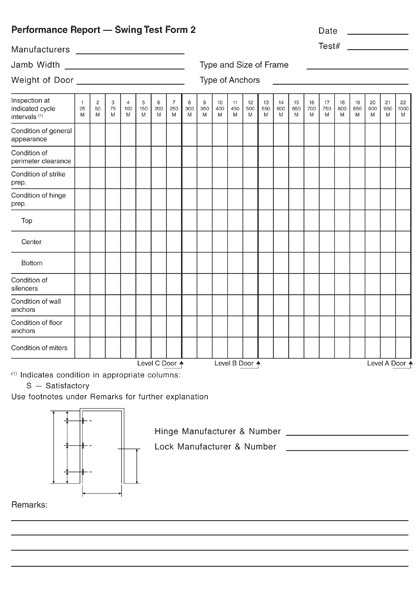
Unless specified otherwise, the test shall be performed on a 3‘-0“ x 7‘-0“ nominal size frame having a 5 3/4“ jamb depth. A detailed description of the door frame and the applicable processes such as welding, bonding, etc. used for attaching components, shall be recorded in the report, Swing Test Form 2, under the “remarks” section.
A detailed description of the frame and anchoring system which shall cover all details of the anchors, as well as the means of attachment in the frame and the weight of the door used for the test shall be recorded in the test report, Swing Test Form 2.
5. Swing test
5.1 Doors
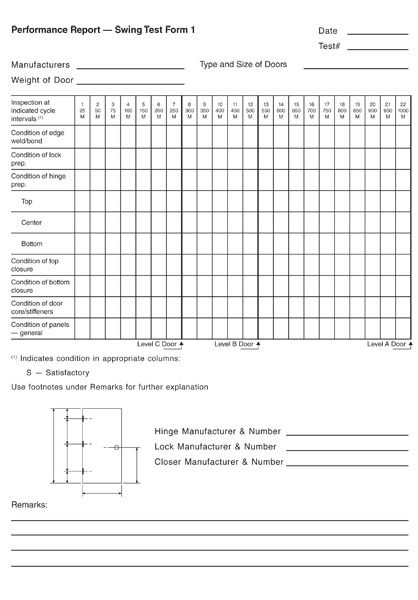
Duration of the test shall be 250,000 cycles with latching for Level C doors; 500,000 cycles with latching for Level B doors; and 1,000,000 cycles with latching for Level A doors. A general inspection of the door shall be made at 25,000 cycle intervals for the first 100,000 cycles and at 50,000 cycles thereafter. A mechanical counter or equivalent shall be used to record the cycles.
The general inspection shall cover perimeter clearances between door and frame and all components readily accessible, such as door face skins, exposed hinge and lock stiles, flush closing channels, end closures, hinge reinforcements, and lock body/face plate reinforcements and shall cover the integrity of assemble methods used to connect the door components.
Doors which have passed the cycling criteria at one level shall be deemed to have passed all lower levels. The results shall be recorded on a standard performance report, Swing Test Form 1.
5.2 Frames and frame anchors
Duration of the test shall be 250,000 cycles for Level C frames; 500,000 cycles for Level B frames; and 1,000,000 cycles for Level A frames. A general inspection of the frame shall be made at 25,000 cycle intervals for the first 100,000 cycles and at 50,000 cycle intervals thereafter.
The general inspection shall cover perimeter clearances between door and frame and all frame components readily accessible, such as corner clips and screws, corner tabs and slots, head and jamb tabs/slots hinge reinforcements, and strike reinforcements and shall cover the integrity of assembly methods used to connect the frame components.
Door frames which have passed the cycling criteria at one level shall be deemed to have passed all lower levels. The results shall be recorded as part of the test report, Swing Test Form 2.
6. Twist test
The twist test is applicable in evaluating door construction only.
The deterioration of the door strength during the cycle test, if any, shall be checked through a series of twist tests. These twist tests shall be performed before the cycle test begins and then at 25,000 cycle intervals for the first 100,000 cycles and at 50,000 cycle intervals for the balance of the test.
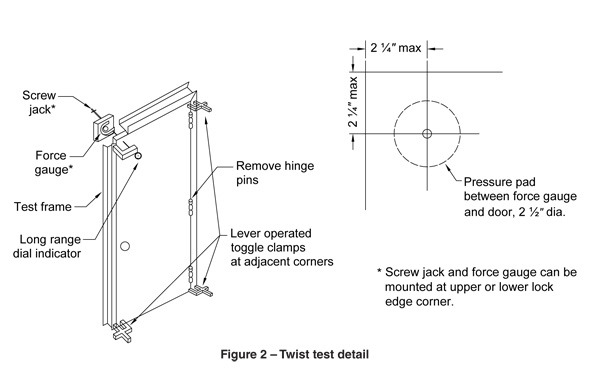
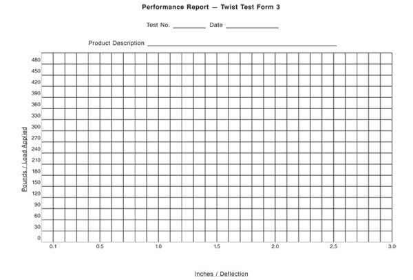
During the twist test, the hinge pins and silencers shall be removed from the door and frame assembly and the exit device shall be unlatched. The door is then clamped in place as noted in figure 2. If necessary to facilitate twist testing, the door is permitted to be taken from the test fixture and installed in a separate twist fixture. Loads in 30 lb. increments shall be applied at the upper or lower lock edge corner through the screw jack and force gauge in the area illustrated in figure 2. The deflection noted on the dial indicator shall be plotted against the load applied to the corner on Twist Test Form 3. A maximum 300 lb. load shall be applied. The load shall then be reduced in 30 lb. increments and corresponding deflections recorded and plotted on Twist Test Form 3. A smooth curve drawn through the points shall graphically demonstrate the reaction of the door to increasing and decreasing pressures at different cycle intervals.
At the completion of each twist test, the hinges shall be reassembled by means of inserting the hinge pins, silencers shall be reinstalled, the exit devise shall be latched, and the assembly shall be subjected to another 25,000 or 50,000 cycles. The condition of the silencers shall be noted and replacements made where deemed necessary.
7. Acceptance criteria
7.1 Doors
7.1.1 — Doors shall not show any visual indication of metal fatigue, cracking or deformation at hardware cutouts or along form contours. Door must remain operable during the test. If the door fails to operate, it will be deemed to have passed the last passed cycle.
7.1.2 — Doors of laminated construction (cores laminated to face sheets, channels or stiffeners laminated to face sheets, etc.) shall not delaminate in excess of 10% of the total surface area. (Strike the door surface softly with a mallet to identify delaminated areas, if any).
7.1.3 — In doors of welded construction (stiffeners or channels welded to face sheets, etc.) breakage of welds shall not exceed 10% of the total weld of those face stiffeners.
7.1.4 — Top, bottom or edge channels shall remain securely in place, without any weld breakage.
7.1.5 — Where seams occur on doors, there shall be no opening or spreading of the seam.
7.1.6 — All hardware reinforcements shall remain securely in place and show no visual signs of metal fatigue, cracking or deformation.
7.1.7 — As a result of the twist test, the maximum deflection permitted shall not exceed 2 1/2“ when loaded to 300 lb. for Level C. For Level B and Level A doors the maximum deflection shall not exceed 1 1/4“ when loaded to 300 lb.
7.1.8 — Permanent deflection for doors shall not exceed 1/8“ when load is removed after each twist test..
7.1.9 — Tapped holes shall not strip.
7.1.10 — At the completion of the swing and twist tests, the door shall be fully operable. If the door becomes inoperable, the door will be considered to have failed and the previous passed cycle will be recorded.
7.1.11 — Upon completion of the foregoing checks and measurements, remove door from test structure and cut door into four equal sections with a horizontal and a vertical cut at the center of the door height and door width. Internal construction of door shall be inspected visually for delamination, metal fatigue, cracking and weld failure. The results of this inspection shall be recorded in the test report.
7.2 Frames and frame anchors
7.2.1 — Frames shall remain plumb, square, rigid, and show no visual signs of metal fatigue, cracking, or deformation at hardware provision cutouts or along form contours.
7.2.2 — Corners shall stay aligned with seams in a closed position.
7.2.3 — Perimeter clearances between door and frame shall not be greater than 1/16“ from those listed at onset of test.
7.2.4 — All hardware reinforcements shall remain securely in place and show no visual signs of metal fatigue, cracking or deformation.
7.2.5 — Tapped holes shall not strip.
7.2.6 — At any time during the test, the frame shall not limit door operation. If during the test the door becomes inoperable, it shall be determined whether a defective door frame, hardware reinforcement, hinge, frame anchor, etc., caused the failure and shall be so noted in the test report.
Annex A
(informative)
Acceptance Criteria for Laminated Doors
Doors of laminated construction (cores laminated to face sheets, channels or stiffeners laminated to face sheets, etc.) shall not delaminate in excess of 10% of the total laminated surface area.