American National Standard
Testing and Rating of Severe Windstorm Resistant Components for Swinging Door Assemblies for Protection of Building Envelopes
(Not applicable for FEMA 320/361 or ICC-500 Shelters)
ANSI/SDI A250.13-2008 (R2018)
1 Scope
1.1 This standard provides procedures for testing and establishing load ratings (design pressure in pounds per square foot or design load in pounds force) for components of exterior swinging door assemblies for purposes of protection of openings in building envelopes during severe windstorm conditions, such as a hurricane, that produces sustained wind speeds or gusts in a range of 110 to 150 miles per hour as defined by ASCE 7. It is not intended to simulate wind forces generated by tornadoes. These products are for non-life safety installations and not for use in storm shelters. Life Safety/Shelter products must meet FEMA 320/361 and/or ICC-500.
1.2 The procedures cover all components normally assembled to form an exterior swinging door system. This includes door frames, hardware mullions, thresholds, frame anchorage, hinges, locksets, latches and bolts, doors, sidelights, transoms and glazing systems. This procedure applies to both single swing and pair assemblies and also includes procedures for testing and rating components for both in-swing and out-swing installations.
1.3 The evaluations required by this standard are based on the performance tests specified in ASTM E1886, ASTM E1996 and ASTM E330.
1.4 Evaluations under this procedure are designed to determine the ability of exterior doors to remain closed under conditions present in severe windstorms, including high, fluctuating wind speeds and the presence of wind-born debris. Assemblies meeting these requirements are less likely to open during a storm, preventing potentially large pressure differentials which may cause or contribute to major structural damage. This procedure does not consider it necessary for the door assembly to be capable of preventing water intrusion as a result of severe windstorm exposure conditions.
It is recognized that products and assemblies meeting these requirements will not necessarily prevent all forms of damage associated with hurricanes and other severe windstorms. It is also assumed that these assemblies themselves might be damaged in a severe windstorm to an extent that would require repair or replacement after such an event.
2 Definitions
Building Envelope: Windows, doors, curtain walls, wall and roof assemblies.
Classified: Products or materials of a specific group category that are constructed, inspected, tested and subsequently reinspected in accordance with an established set of requirements. The classification process is performed by an organization acceptable to the authority having jurisdiction.
Component: Any of several manufactured items, classified / listed and labeled, used in the construction and installation of a swinging door assembly. Components include door frames, doors, hardware, glazing systems and similar products normally supplied separately to a job-site where they are assembled and / or installed to form a complete assembly.
Design Load: The specified point force applied to a product. Units of measure are pounds force (lbf).
Design Pressure: The specified force applied to a specified unit area of product surface. Units of measure are pounds-force per square foot (psf).
Impact Energy (Kinetic Energy – KE): The specified dynamic load applied to a product. Units of
measure are foot-pounds (ft-lbf).
In-Swing Door: A door with the push side on the exterior or that swings into the building when opened. Negative pressure acts to close this door and positive pressure acts to open this door.
Labeled: Equipment or materials to which has been attached a label, symbol, or other identifying mark of an organization that is acceptable to the Authority Having Jurisdiction (AHJ) and concerned with product evaluation, that maintains periodic inspections of production of labeled equipment or materials, and by whose labeling the manufacturer indicates compliance with appropriate standards or performance in a specified manner.
Listed: Equipment materials or services included in a list published by an organization that is acceptable to the Authority Having Jurisdiction (AHJ) and concerned with evaluation of products or services, that maintains periodic evaluation of services and whose listing states that either the equipment, material, or service meets identified standards or has been tested and found suitable for a specified purpose.
Operable: Capable of being opened by the application of ordinary levels of applied force to the latch operator and door assembly.
Note: Door assemblies that have been subjected to the severe conditions of the tests involved in this method are not expected to be undamaged and thus will normally not operate with the low force levels generally required for undamaged assemblies. The goal is to provide an assembly that will remain closed during the windstorm, but not be damaged to the extent that it requires the use of tools to be opened after the event.
Out-Swing Door: A door with the pull side on the exterior or that swings away from the building when opened. Negative pressure acts to open this door and positive pressure acts to close this door.
Severe Windstorm: A weather event such as a hurricane that produces sustained wind speeds or gusts in a range of 110 to 150 miles per hour.
Stiffness Classification: A measure of a door’s resistance to bending as determined by a twist test under a prescribed loading condition.
3 General
3.1 Units of Measurement
3.1.1 When a value for measurement is followed by a value in other units in parentheses, the second value is only approximate. The first stated value is the requirement. The primary units are inch-pound. Appendix A contains a table of the Imperial values used in this standard and corresponding SI values.
3.1.2 Unless specifically indicated otherwise, tolerances shall be in accordance with Appendix A.
3.1.3 Where load ratings are to be applied in units of pounds per square foot (psf), these values shall be expressed in 5-pound-per-square-foot increments. For components that are rated in terms of pounds force, values shall be expressed in 10-pound increments. All rated values shall be determined by rounding down from values derived from tests.
3.2 Referenced Standards
3.2.1 ANSI/ASCE 7-10, Minimum Design Loads for Buildings and Other Structures
3.2.2 ANSI/SDI A250.4-2011, Test Procedure and Acceptance Criteria for Physical Endurance for Steel Doors, Frames, Frame Anchors and Hardware Reinforcings
3.2.3 ASTM E330-02 (2010), Standard Test Method for Structural Performance of Exterior Windows, Doors, Skylights and Curtain Walls by Uniform Static Air Pressure Difference
3.2.4 ASTM E1886-05, Standard Test Method for Performance of Exterior Windows, Curtain Walls, Doors, and Storm Shutters Impacted by Missile(s) and Exposed to Cyclic Pressure Differentials
3.2.5 ASTM E1996-12a, Standard Specification for Performance of Exterior Windows, Curtain Walls, Doors and Storm Shutters Impacted by Windborne Debris in Hurricanes
3.2.6 ASTM F476-84 (2002) Standard Test Methods for Security of Swinging Door Assemblies
3.2.7 ANSI/BHMA A156.1-2013, Butts and Hinges
3.2.8 ANSI/BHMA A156.16-2008, Auxiliary Hardware
3.3 Undated References
3.3.1 References to standards listed above shall be to the edition indicated.
4 Overview
4.1 The procedures in this document are designed to evaluate each critical component used in a swinging door assembly for the component’s ability to perform its intended function. The evaluation is conducted under the conditions of stress and loading the component would be subjected to in the testing of a complete assembly under the assembly test methods commonly specified for severe windstorm resistance.
4.2 The tests and evaluations required by this procedure include both the application of engineering safety factors and worst-case analysis to ensure that component substitutions in field assemblies will perform to the minimum levels expected.
4.3 Components evaluated by this method are classified into various strength categories that can be used to determine assembly ratings. A single component may have multiple ratings depending on various parameters such as size, number and location of anchors or fasteners, type of surrounding construction and other factors. Proper application of these ratings allows for the determination of an assembly’s design pressure rating and minimum impact energy resistance. These ratings are intended to be used to determine compliance with code requirements developed for complete assemblies.
4.3.1 Doors are rated for design pressure in pounds per square foot (psf), impact energy in foot-pounds (ft-lbf) and stiffness classification. Stiffness is required in determining the interaction between the door bending under load, transmission of impact energy to latching hardware and frames, and latching engaugement.
4.4 Proper application of this standard requires a basic level of understanding of physics, mechanics and materials science.
4.5 This procedure provides specific tests and rating methods for the following components:
Section 5 – Door Frames
Section 6 – Hinges
Section 7 – Latching Hardware
Section 7.1 – Locksets (Bored, Mortise, Deadbolts)
Section 7.2 – Single Point Rim or Mortise Exit Devices
Section 7.3 – Multi-point Latches (including flush
and surface bolts)
Section 8 – Doors
Section 9 – Door Light Kits
Section 10 – Sidelight and transom frames
Section 11 – Miscellaneous Components
Section 11.1 – Hardware Mullions
Section 11.2 – Thresholds
5 Door Frames
5.1 Frames are to be evaluated in the largest door opening sizes, minimum jamb depth and minimum frame material thickness for which a design rating is to be determined. Frames intended for use in both single swing and pair assemblies shall be tested in both configurations. Frames are to be installed following the manufacturer’s written instructions which are to include:
a) Wall substrate – wood/steel stud, concrete, masonry, structural steel.
b) Anchors – number, size, type and spacing of anchors, anchor or bolt embedment, and number and type of fasteners required at each anchor location.
c) Reinforcements – location and attachment.
d) Gasketing – location, type and attachment.
e) Hinges – number, type, size and locations.
f) Latching Hardware – type and location.
5.2 Test Procedure
5.2.1 Static Pressure Test
5.2.1.1 The frame shall be installed into a test unit constructed to simulate the wall design specified by the frame manufacturer. The frame installation shall be in accordance with the frame manufacturer’s written instructions (refer to figure 1 for typical details). For wall designs that differ significantly from those shown, the test installation shall simulate actual intended wall design and anchorage.
A flush door rated for not less than the desired frame design pressure shall be mounted with the number of hinges specified by the frame manufacturer. For single-swing frames, a single-point simulated latch and a stainless steel strike shall be installed between 38″ and 42″ above the bottom of the frame (see figure 2.) The door and latching hardware shall be of sufficient strength so that they do not fail at the required test load. Door (s) shall be installed in the direction of swing for the desired listing.
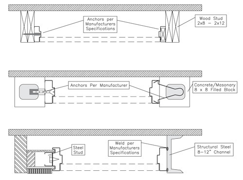
Figure 1 – Wall Substrates for Frame Tests
5.2.1.2 For pair frames, two flush doors rated for not less than the desired frame design pressure shall be installed with a simulated latching arrangement with a top and bottom bolt on the inactive door and a single point latch on the active door latching into the inactive door. The doors used are to be reinforced as described in 5.2.1.2.1 and latched as shown in figure 2.
If the manufacturer specifies other latch/lock locations, tests shall be conducted under specified conditions and the resulting rating shall specify the latching requirements.
5.2.1.2.1 The flush door used shall be reinforced along the latch or meeting edge by bolting a 1-1/4 inch by 1-1/4 inch by 3/16 inch structural steel angle to both faces of the door with 1/4-20 bolts at 16 (±) 1 inches on center and within 6 (±1) inches of the corners. The angle shall be placed such that the free leg of the angle is oriented toward the edge of the door and is located at 3 inches from the door latch edge (see figure 2).
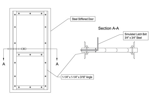
Figure 2 – Door Reinforcement for Frame Tests
5.2.1.3 The frame and door assembly shall be installed in a static pressure test chamber per the requirements of ASTM E330.
5.2.1.4 The assembly shall be subjected to a static pressure equal to 1.5 times the design pressure rating specified by the frame manufacturer under both positive and negative pressure. Each pressure cycle shall be applied for a minimum of 30 seconds, then released and reduced to zero.
5.2.1.5 At the conclusion of this test, the frame shall not prevent the door (s) from operating after the simulated latch bolt (s) has been retracted and a 15 pound force is applied at the mid-height of the door, horizontally 1 inch from the lock edge. The frame shall remain in the opening.
5.2.2 Impact Test
5.2.2.1 Upon completion of the static pressure test an identical assembly shall be subjected to impacts with an impact energy of 350 foot-pounds. The impact energy shall be delivered by one of the following two methods:
Method 1 – Deliver impact energy by a 100-pound total weight pendulum impactor fitted with a number 2 or better, 12-inch-long Douglas Fir or Southern Yellow Pine, nominal 2 by 4 striking face. The pendulum is to be suspended in a manner that assures a direct normal impact to the door assembly. Refer to ASTM F476 for details of a comparable pendulum impact device (see figure 3)
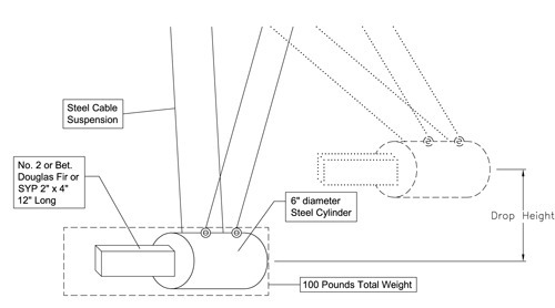
Figure 3 – Pendulum Impactor
Method 2 – Deliver the impact energy in accordance with the impact method defined in ASTM E1996 using a 9 pound 2 x 4 missile impacting end-on at a velocity of 50 feet per second.
5.2.2.2 Impacts are to be delivered to the exterior side of the door (s) per ASTM E1886. Impact locations
as described below and as shown in figure 4).
5.2.2.2.1 Single Frames
Five impacts in accordance with Figure 4.
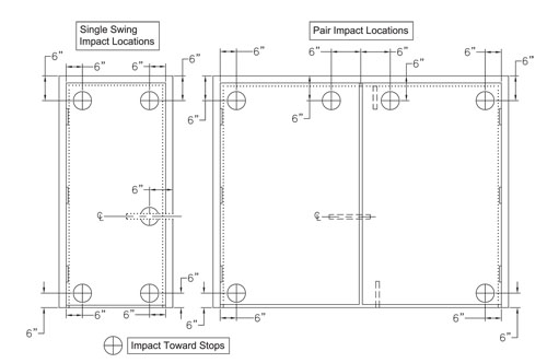
Figure 4 – Impact Locations for Frame Tests
5.2.2.2.2 Pair Frames
Six impacts in accordance with Figure 4.
5.2.3 At the conclusion of this test, the frame shall not prevent the door (s) from operating after the simulated latch bolt (s) has been retracted and a 15-pound force is applied at the mid-height of the door, 1 inch horizontally from the lock edge. The frame shall remain in the opening.
5.3 Cycle Test
5.3.1 Upon completion of the impact tests specified in 5.2, the same assembly shall be subjected to the pressure cycling test specified in ASTM E1886.
5.3.2 At the conclusion of this test, the frame shall not prevent the door (s) from operating after the simulated latch bolt (s) has been retracted and a 15-pound force is applied at the mid-height of the door, 1-inch horizontally from the lock edge. The frame shall remain in the opening.
5.4 Frame Ratings
5.4.1 Frames that meet the criteria specified in this section shall be rated for the design pressure attained in the evaluation and for impact energy resistance. Ratings shall be specific to positive and negative design pressure configuration (single/ pair, in-swing/out-swing) and shall apply to all overall frame sizes (not to exceed either height or width of frame tested) equal to or smaller than the frame tested.
6 Hinges
6.1 Leaf Hinges
Three representative specimens shall be tested. Ratings shall be based on the lowest load successfully
sustained by all three specimens.
6.1.1 Impact Test
6.1.1.1 Hinges shall be mounted for testing in the test fixture shown in figure 5. Hinges are to be mounted to the simulated frame and door sections using screws provided by the hinge manufacturer.
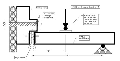
Figure 5 – Hinge Structural Load Test Fixture
6.1.1.2 One 125 foot-pound impact shall be delivered to the simulated door section at a point 6 inches from the hinge centerline using the pendulum impactor specified in figure 3. Shearing of any fastener or deformation of the hinge which renders the hinge inoperable shall constitute a failure. The simulated door section shall be tested as an in-swinging door.
NOTE: Impact energy specified delivers approximately twice the energy to the hinge as occurs in a typical door assembly test using a 9 pound 2 x 4 missile at 50 feet-per-second.
6.1.1.2.1 Exception
Hinges listed only for use in out-swing door assemblies do not require an impact test.
6.1.2 Structural Load Test
6.1.2.1 The test assembly described in 6.1.1.1 shall be mounted in a testing machine and loaded at a rate of 0.05 inches per minute until failure. The load shall be applied through a 3/4-inch diameter roller and 1/4-inch thick by 3-inch wide steel plate in a manner that places the attachments in shear on the push side of the simulated door section. The load at failure shall be recorded.
6.1.3 Rating
6.1.3.1 Hinges shall be rated for a design load based on the lowest ultimate load value determined in 6.1.2.1, divided by a safety factor of 1.5.
6.2 Continuous Hinges and Pivots
6.2.1 Continuous hinges and/or pivots shall be tested in the maximum length with the minimum number of fasteners supplied by the manufacturer. Continuous hinges and/or pivots are to be tested applied to a simulated door as described in section 5.2.1.1 and a frame assembly designed to withstand the loads required to evaluate the hinge and/ or pivots to the level required. A simulated frame constructed from 4-inch to 6-inch wide structural steel channel and with a solid steel stop 1-inch wide by 5/8-inch high is suitable for this purpose. Pivots and continuous hinges shall be tested using the maximum size of door for which a rating is desired.
6.2.2 Static Pressure Test
6.2.2.1 Apply a pressure equal to 1.5 times the hinge manufacturer’s specified design pressure per ASTM E330 in both positive and negative directions. Hold each load for a minimum of 30 seconds, then release.
6.2.3 Impact Test
6.2.3.1 Using either the same assembly used for the static pressure test or an identical assembly, at the manufacturer’s option, conduct three impact tests using one of the impact test methods described in 5.2.2.1 at the following locations against the push side of the door.
6.2.3.1.1 Impact 6 inches down from the top and 6 inches horizontally from the hinge edge of the door.
6.2.3.1.2 Impact the mid-height of the door 6 inches from the hinge edge.
6.2.3.1.3 Impact 6 inches up from the door bottom and 6 inches from the hinge edge.
6.2.4 Cycle Test
6.2.4.1 Upon completion of the impact tests, the same assembly shall be cycled per ASTM E1886.
6.2.5 Throughout the tests described in section 6.2 the door shall remain secured in the frame and shall be operable at the conclusion of the tests.
6.2.6 Rating
6.2.6.1 Continuous hinges and pivots shall be rated for the impact energy resistance in foot-pounds and design pressure in pounds per square foot and maximum size, based on the tested assembly size for which they successfully complete the required testing.
7 Latching Hardware
7.1 Locksets
7.1.1 Impact Test
7.1.1.1 Locksets shall be mounted in the test fixture described in figure 6. Mounting shall be in accordance with the lock manufacturer’s instructions. Locksets are to be in the locked mode for all tests.
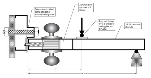
Figure 6 – Lockset Test Fixture
7.1.1.2 Strikes shall be mounted to the simulated frame section using the screws provided by the lock manufacturer.
7.1.1.3 One 125 foot-pound impact shall be delivered to the test fixture (push side) at a point 6 inches from the simulated door edge using the pendulum impactor specified in figure 3. If the lockset handle or other parts are in the indicated impact area, the impact location shall be moved upward sufficiently to avoid hitting the parts.
NOTE: Impact energy specified delivers approximately twice the energy to the latch as occurs in a typical door assembly test using a 9 pound 2 x 4 missile at 50 feet-per-second.
7.1.2 Structural Load Test
7.1.2.1 Upon completion of the impact test specified in section 7.1.1, the test fixture and the same specimen (figure 6) shall be mounted in a testing machine. A load shall then be applied equal to 1.5 times the manufacturers’ designated design load. The load shall be applied through a 3/4-inch roller and 1/4-inch by 3-inch steel loading plate of sufficient width to span the simulated door portion of the test fixture. This load shall be held for 30 seconds and then released.
7.1.2.2 Upon completion of the structural test the lockset shall be operable.
7.1.3 Lockset Rating
7.1.3.1 The lockset rating shall be the design load and impact energy specified by the manufacturer and verified by acceptable results in the impact and structural load test described in this section.
7.2 Single Point Rim and Mortise Exit Devices
7.2.1 Single point rim and mortise exit devices shall be mounted on a door of the stiffness classification and maximum size for which a rating is to be determined. Mounting shall be in accordance with the device manufacturer’s instructions.
7.2.2 Impact Test
7.2.2.1 One 350 foot-pound impact shall be delivered to the pull side of the door using one of the impact test methods described in section 5.2.2.1. If hardware location interferes with the specified locations for impacts the impact shall be located as close to the specified location as possible in a manner that avoids impact on the hardware.
7.2.2.2 Upon completion of the impact tests the door shall remain latched and the single point rim or mortise exit device shall be operable.
7.2.3 Static Pressure Test
7.2.3.1 Upon completion of the impact tests specified in 7.2.2.1, the same assembly shall be mounted in a static pressure test chamber and tested per ASTM E330.
7.2.3.1.1 Apply 1.5 times the manufacturer’s specified design pressure to the push side of the door. Hold for a minimum of 30 seconds and release.
7.2.3.1.2 Upon completion of the test the single point rim or mortise exit device shall be operable.
7.2.4 Rating of Single Point Rim and Mortise Exit Devices
7.2.4.1 Single point rim or mortise exit devices shall be rated for the design pressure in pounds per square foot, impact energy resistance in foot-pounds, maximum pair or single door leaf size, and door stiffness classification specified by the device manufacturer and verified by acceptable results in the impact and structural load test described in this section.
7.3 Multi-Point Latches
7.3.1 Multi-point latches shall be mounted on the maximum size pair of the minimum stiffness class doors specified by the manufacturer for testing.
Note: Since many exterior doors are used as a required “means of egress”, building codes do not generally
allow the use of additional manual bolts and locks on these doors. That is, it must be possible, under emergency conditions, for these doors to be opened with a single manual operation. The use of auxiliary latching devices as a means of increasing the windstorm resistance rating of an assembly should be verified for acceptability under prevailing building code requirements.
7.3.2 Impact Test
7.3.2.1 The door containing the device under test (active leaf) shall be subjected to three 350 footpound impacts using one of the impact test methods described in Section 5.2.2.1 to the pull side of the door. One impact is to be made at the upper meeting edge of the door 6 inches below the top edge of the door and 6 inches from the meeting edge. The second impact is to be made at the lower meeting edge of the door 6 inches above the bottom and 6 inches from the meeting door edge. The third impact is to be made at the center of the door opposite and 5 inches below the push bar. If hardware location interferes with the specified locations for impacts the impact shall be located as close to the specified location as possible in a manner that avoids impact on the hardware.
7.3.2.2 When other hardware is being evaluated simultaneously with bolts (surface or flush type) to increase the overall rating, then a fourth impact is to be made at the centerline of the other hardware and 6 inches from the meeting door edge.
7.3.2.3 Upon completion of the impact tests the multi-point latch shall be operable.
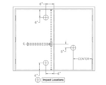
Figure 7 – Impact Locations for Multi-Point Latch Test
7.3.3 Static Pressure Test
7.3.3.1 Upon completion of the impact test, the same assembly shall be tested on the impact assembly or mounted in a test chamber and tested per ASTM E330 under uniform static pressure.
7.3.3.2 Starting at the design pressure specified by the manufacturer, apply the pressure in 5 psf increments in both positive and negative directions until failure occurs. Each pressure increment shall be held for a minimum of 10 seconds in each direction.
7.3.3.3 After each pressure increment, remove the pressure and check the hardware for operability. One pressure increment consists of both a positive and negative pressure.
7.3.3.4 Record mode of failure and pressure increment at failure.
7.3.4 Multi-Point Latch Rating
7.3.4.1 Multi-point latches shall be rated for the impact energy resistance in foot-pounds and design pressure in pounds per square foot as follows:
7.3.4.1.1 For pairs of doors with four or more points of latching, the design pressure is the maximum test pressure increment that did not result in failure as determined by 7.3.3.3 divided by a safety factor of 1.5.
7.3.4.1.2 For pairs of doors with single point latching on the active leaf and multi-point latching on the inactive leaf as described in 7.3.2.1, the design pressure is the maximum test pressure increment that did not result in failure as determined by 7.3.3.3 divided by a safety factor of 1.5.
7.3.4.1.3 For pairs of doors with single point latching on the active leaf and multi-point latching on the inactive leaf as described in 7.3.2.2 with surface or flush bolts per ANSI/BHMA A156.16 Auxiliary Hardware, mounted on the inactive leaf, the design pressure is the maximum pressure increment that did not result in failure as determined by 7.3.3.3 divided by a safety factor of 3.0.
8 Doors
8.1 Doors shall be tested in the largest size (overall area, greatest width, greatest height) for which a design pressure rating is to be applied. Requirements for framing systems or other reinforcements in doors shall be specified as defined in the manufacturer’s follow-up inspection procedures. All doors of the same design with smaller dimensions shall be given the same rating as the test door(s).
8.2 Stiffness Classification
8.2.1 Doors shall be classified for stiffness by performing the following twist test on a 3’0″ by 7’0″ sample of the full flush panel (no hardware preparations) door construction under investigation.
8.2.1.1 Mount the door panel in a rigid test frame and clamp the bottom two corners and one top corner securely to the frame.
8.2.1.2 Apply a load of 300 lbf through a 2.5 inch diameter by 1/4-inch thick steel pad to a point centered 3 inches down and 3 inches horizontally from the free corner of the door per ANSI A250.4.
8.2.1.3 Measure the door deflection at the free corner, as described in ANSI A250.4, to the nearest 0.01 inch.
8.2.2 Classifications
8.2.2.1 Doors shall be classified for stiffness as follows in Table 1 based on the results of the twist test.
Table 1 – Stiffness Classification
| Corner Deflection | Stiffness Class |
| ≤ 0.5 inch | I |
| > 0.5 inch and ≤ 1.0 inch | II |
| > 1.0 inch and ≤ 2.0 inches | III |
| > 2.0 inches and ≤ 3.0 inches | IV |
| > 3.0 inches | V |
8.3 Assembly Tests
8.3.1 Doors shall be installed in each assembly configuration for which a rating is to be determined. The following list shall be used to select the test configurations.
8.3.1.1 Single-swing with cylindrical single-point latch.
8.3.1.2 Single-swing with mortise single-point latch.
8.3.1.3 Single-swing with rim or mortise exit device.
8.3.1.4 Pairs of doors swinging in the same direction with 4-point latching – surface rods.
8.3.1.5 Pairs of doors swinging in the same direction with 4-point latching – concealed rods.
8.3.1.6 Pairs of doors swinging in the same direction with 3-point latching – surface rods by cylindrical latch.
Table 2 – Example Door Rating Data
| Door Model: 1234 | Stiffness Class II | ||||
| Configuration | Maximum Size | Latch Throw Min. (in) | Latch Strength Min. (lbf) | Impact (ft-lbf) | Design Pressure (psf) |
| Single Out-swing (cylindrical) | 4-0 x 8-0 | 1/2 | 1600 | 350 | 100 |
| Single In-swing (mortise) | 4-0 x 8-0 | 1/2 | 1600 | 350 | 100 |
| Single Out-swing (Rim) | 3-0 x 8-0 | (1) | (1) | 350 | 80 |
| Pair w/ 4-Point (CVR by CVR) | 8-0 x 8-0 | (1) | (1) | 350 | 80 |
| Pair w/ 3-Point | 8-0 x 8-0 | (1) | (1) | 350 | 80 |
| Pair w/ 4-Point (CVR by CVR) | 6-0 x 7-0 | (1) | (1) | 350 | 140 |
| (1) Components are rated in design pressure (psf) not latch strength (lbf) | |||||
8.3.1.7 Pairs of doors swinging in the same direction with 3-point latching – flush bolts or CVR by mortise latch.
8.3.1.8 Pairs of doors swinging in the same direction with 3-point latching-mortise exit device by surface or concealed exit device.
8.3.1.9 Pairs of doors swinging in the same direction with 2-point latching – rim exit device with removable mullion.
8.3.2 A minimum of 3 assemblies shall be tested for single-swing configurations and a minimum of three assemblies shall be tested for pair configurations. Latching hardware configurations can be varied between the individual assemblies to provide coverage per 8.3.1. This includes combining surface and concealed-rod type hardware in one pair assembly to cover configurations from 8.3.1.4 and 8.3.1.5. The resulting ratings will be determined separately for pair and single-swing configurations. When the three assemblies of one swing type vary, the rating for the door is to be based on the highest design pressure test passed by all three assemblies.
8.3.3 Qualifying Doors for Vision Light Kits – Where doors are to be qualified to receive light kits, at least one assembly shall be tested with maximum light kit size desired. This assembly shall be an assembly or at least one of the assemblies from 8.3.2. Multiple light kit designs and sizes may be tested for multiple ratings. The rating for the door is to be based on the highest design pressure test passed by the glazed assembly, but shall not exceed the rating of the opaque assemblies. The largest size (maximum area, height, and width of exposed light) of the light kit and the minimum stile and rail dimensions shall be defined. Requirements for framing systems or other reinforcements in doors shall be specified as defined in the vision light kit manufacturer’s follow-up inspection procedures.
8.3.4 Doors are to be tested installed in frames using latching hardware and hinges with a design pressure rating greater than or equal to the specified design-pressure rating of the door.
8.3.5 Assemblies which incorporate manual surface bolts or other latching hardware intended only for use in severe storm conditions (hurricanes) shall be evaluated for design pressure strength per ASTM E330 with and without the additional hardware engauged. The ratings for such assemblies shall indicate design pressure for the assembly both with and without the additional hardware.
8.4 Test Procedure
8.4.1 Each assembly configuration shall be tested to 1.5 times the design pressure, per ASTM E330.
8.4.2 Each assembly shall be tested to impact and cyclic load tests as specified in ASTM E1886 and ASTM E1996. (At the discretion of the test sponsor the same or an identical assembly shall be permitted for the structural test.) For doors designated by the manufacturer as either in-swing only or out-swing only, the impact test shall be conducted only from the outdoor side of the assembly. For doors designated as either in-swing or out-swing, the impact tests shall be conducted from the outside (push side) of in-swinging assemblies on two samples and from the outside (pull side) of an out-swinging assembly on the third sample.
8.4.3 Assemblies shall remain closed and latched during the tests specified and the active leaf shall be operable at the conclusion of the tests.
8.5 Ratings of Doors
8.5.1 Ratings of doors shall include the following information (see Table 2):
- Maximum Size;
- Stiffness Classification;
- Design Pressure Rating for each configuration type; (this provides consistency in
language); - Impact Energy Resistance Classification;
- Minimum Latch Throw for single point lock sets;
- Minimum Latch Strength for single point lock sets.
9 Door Light Kits
9.1 Door light kits shall be evaluated as complete glazing systems designed for installation into specific door types. These door types shall have been qualified to receive light kits in accordance with paragraph 8.3.3. Glazing systems shall include all parts necessary to install the glazing in the door. This shall normally include at least a glazing panel, frame, sealant or glazing compound and fasteners. Requirements for framing systems or other reinforcements in doors shall be specified as defined in the manufacturer’s follow-up inspection procedures.
9.1.1 Glazing systems shall be tested in the largest size (maximum area, height, width of exposed light) to be rated in the smallest standard door size (minimum 3’0″ x 7’0″) that can accommodate the glazing system.
9.1.2 Alternately, glazing systems shall be tested as part of door assemblies as defined in paragraph 8.3.3. In this case, the largest size (maximum area, height, and width of exposed light) of the light kit and the minimum stile and rail dimensions shall be defined.
9.2 Test Procedure
9.2.1 Static Pressure Test
9.2.1.1 Each assembly configuration shall be tested to 1.5 times the design pressure, per ASTM E330.
9.2.1.2 Install the glazing system into the type and size of door specified by the glazing system manufacturer.
Three identical assemblies are required. The doors shall be mounted in frames and bucks as required for the standard door test procedure.
9.2.2 Impact Test
9.2.2.1 Test the assembly per ASTM E1886 with the impacts required applied to the center and one corner of the glazing panel in each assembly.
9.2.3 Cycle Test
9.2.3.1 Cycle test each assembly per ASTM E1886.
9.2.3.2 Upon completion of the impact and cycle tests there shall be no failure of the glazing system as defined in the referenced standard ASTM E1996.
9.3 Glazing System Ratings
9.3.1 Glazing systems shall be rated at the design pressure used in the evaluation and shall include minimum door size and maximum glazing dimensions (maximum area, maximum height and maximum width).
10 Sidelights and/or Transoms
10.1 Sidelights and/or transoms shall be tested with doors, to the largest total size (maximum area, height and width) to be rated. Testing shall be performed per ASTM E1886 and ASTM E1996. Doors used in the evaluation assembly shall be rated per this method for at least the design pressure specified for the sidelight/ transom assembly.
10.2 Installation of sidelight and/or transom assemblies shall be per manufacturer’s instructions. Frames for these assemblies shall be evaluated for installation in each wall type for which the product is intended. Installation instructions shall include: glazing material, sealants or glazing compounds, installation procedures, and details of frame anchoring methods.
10.3 Ratings for Sidelight and/or Transom Assemblies
10.3.1 Sidelight and/or transom assemblies shall be rated for design pressure based on tests in accordance with ASTM E1886 and ASTM E1996.
11 Miscellaneous Components
11.1 Center Mullions Prepared for Hardware
11.1.1 Center mullions prepared for hardware shall be tested at the maximum height specified by the manufacturer. Install the mullion in a frame of the maximum width for which a rating is desired following the manufacturer’s instructions. Doors used for this test shall be stiffened as described in section 5.2.1.2.1, except that surface applied reinforcements are to be removed in areas required for mounting the latching device. Doors are to be equipped with rim exit devices or other hardware as specified by the manufacturer
11.1.2 Static Pressure Test
11.1.2.1 Load the assembly to 1.5 times design pressure in accordance with ASTM E330 in both positive and negative directions. The pressure load shall be maintained for a minimum of 30 seconds.
11.1.3 Impact Test
11.1.3.1 On the same assembly used in the structural test or an identical assembly, at the manufacturer’s option, apply four impacts of 350 ft-lbf using one of the impact test methods described in section 5.2.2.1. One impact is to be applied at the meeting edge of the doors 6 inches down from the head jamb. The second impact is to be applied at the meeting edge of the doors 6 inches up from the sill and the third impact applied at the centerline of the latch and 6 inches horizontally from the latch edge of the door. Apply a fourth impact at the center of the other door 5 inches below the latch. Upon completion of the impact tests, conduct cycle testing as specified in ASTM E1886. At the completion of these tests the hardware mullion shall remain in place and the door assembly shall be operable.
11.1.4 Hardware mullions shall be rated for the impact energy successfully passed and for the design pressure tested in the static pressure and cycle tests.
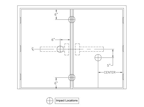
Figure 8 – Impact Locations for Center Mullion Test
11.2 Thresholds
11.2.1 Thresholds are only evaluated for their ability to retain latch bolts and strikes and remain secured to underlying construction when subjected to anticipated structural and impact energy loads.
11.2.2 Thresholds are to be tested in conjunction with hardware mullions as described in section 11.1 when applicable. Thresholds that are designed for direct attachment of latching devices shall be tested as follows.
11.2.3 Thresholds shall be tested at the maximum door opening width to which the resulting rating is to be applied. Thresholds shall be installed in a test assembly using a frame and stiffened doors (per 5.2.1.2.1) known to be capable of sustaining the required test pressure. Thresholds shall be attached to a simulated floor using the number, size and locations of fasteners specified by the manufacturer. The set-up shall be for a single-point latching on the active leaf and two-point latching on the inactive leaf with the bolt and strike specified by the manufacturer.
11.2.4 Static Pressure Test
11.2.4.1 The test assembly shall be loaded per ASTM E330 to 1.5 times the design pressure specified by the manufacturer in both positive and negative directions. The pressure in each direction shall be maintained for a minimum of 30 seconds, then released.
11.2.5 Impact Test
11.2.5.1 The same assembly or an identical assembly which has not been subjected to the 1.5 times design load test shall be used for this test at the manufacturer’s option. Impacts (350 ft-lb) shall be applied using one of the impact test methods described in section 5.2.2.1 to a location on the centerline of any latching device that engauges into the sill at a point 6 inches up from the sill. If the assembly includes two latching locations, two impacts are required.
11.2.6 Cycle Test
11.2.6.1 The same assembly used for the impact test in 11.2.3 shall be subjected to the cyclic pressure
test prescribed by ASTM E1886.
11.2.7 Upon completion of these tests, the door assembly shall be operable and the threshold shall remain in place.
11.2.8 Thresholds shall be rated for the impact energy successfully passed and for the latching load established in the structural load and cycle tests. Latching load (lbf) shall be calculated as design pressure (psf) times the area (square feet) of the opening divided by 4 (the equivalent of one quarter of the total load).
12 Selection Criteria
12.1 The following process is used to determine Swinging Door Assembly Ratings for Severe Windstorm
Resistance from Component Ratings.
12.1.1 The first step in determining if an assembly meets a code requirement for severe windstorm resistance is for the building designer to determine the required performance level for the opening. This shall include a calculation of the required minimum design pressure in pounds per square foot and the determination of whether or not impact resistance is required. In most cases ASCE 7 is specified by the applicable building code and requires a thorough analysis of the building design and location to determine design pressure for each opening. State and local building codes will generally specify when impact resistance is required and at what level.
12.1.2 If impact resistance is required, each component of the opening shall have an impact rating equal to or greater than the impact energy required for the opening.
12.1.3 Determine the wall construction type for the opening (masonry, wood frame, steel, etc.). The selected frame and anchorage method must meet or exceed the design pressure and impact energy requirements for the opening. The size at which the frame is rated must be equal to or greater than the size requirement for the opening.
12.1.4 Determine the type of hinge needed for the application. Leaf and butt hinges are expressed in lbs force. To select leaf or butt hinges, multiply the design pressure by the tributary area in square feet for each hinge to determine the required hinge design load in pounds force (lbf). Select a hinge that meets or exceeds the design load and impact energy requirements for the opening (see examples in Appendix B).
12.1.4.2 Continuous hinges and pivots are rated for design pressure, impact energy and door leaf size. The design pressure and impact energy rating for the selected continuous or pivot hinge must meet or exceed the requirements for the opening. The required door size for the opening must be equal to or less than the door size listed for the hinge.
12.1.5 To select cylindrical lock or mortise lock for a door leaf, determine the latch bolt design load (lbf) required, by multiplying one-half of the nominal door leaf area in square feet by the design pressure. Select a lock with a design load rating (lbf) equal to or greater than the calculated latch design load (see examples in Appendix B).
12.1.6 To select a rim exit, mortise exit, hardware mullion, or multi-point latch configuration, compare the rated hardware design pressure, impact energy requirement, and door size with the opening requirements. The selected hardware design pressure and impact energy requirements must meet or exceed the design pressure and impact energy requirements for the opening. The required door size for the opening must be equal to or less than the door size listed for the selected hardware.
NOTE: Stiffness classifications are only required for rim and mortise exit devices.
12.1.7 If a light kit is to be installed, select a light kit with a design pressure and impact energy rating equal to or greater than the required values.
12.1.8 To select a door leaf compare the rated design pressure, desired hardware configuration, impact energy, and size requirements with the opening requirements. Obtain the design pressure rating for the specified hardware configuration by checking the door rating data (see example in table 2). The rated door panel design pressure for the desired hardware configuration, impact energy, and size must meet or exceed the requirements for the opening. If rim exits or mortise exits are specified, the door panel must meet or exceed the door stiffness classification for the rim or mortise exit device being used.
12.1.9 All components must be installed in accordance with the component manufacturer’s instructions. The assembly rating is equal to the lowest design pressure rating of the selected components and must be equal to or greater than the design pressure required for the opening.
Appendix A
(informative)
Tolerances and Conversion of Measurements to SI
| I-P Value | 0.05I-P Unit300 | I-P Tolerance | SI Value | SI Unit | SI Tolerance |
| 110 | MPH | NA | 49 | M/s | NA |
| 150 | MPH | NA | 67 | M/s | NA |
| 5 | PSF | ±0.5 | 239 | Pa | ±24 |
| 10 | PSF | ±0.5 | 479 | Pa | ±24 |
| 60 | in | ±0.25 | 1524 | mm | ±6 |
| 30 | in | ±0.25 | 762 | mm | ±6 |
| 40-5/16 | in | ±1/8 | 1024 | mm | ±3 |
| 1-1/4 | in | ±1/8 | 32 | mm | ±3 |
| 3/16 | in | ±1/32 | 4.8 | mm | ±1 |
| 16 | in | ±1 | 406 | mm | ±25 |
| 6 | in | ±1 | 152 | mm | ±25 |
| 3 | in | ±1/8 | 76 | mm | ±3 |
| 15 | lbf | ±0.5 | 67 | N | ±2 |
| 1 | in | ±1/16 | 25 | mm | ±2 |
| 350 | ft-lb | ±3.5 | 475 | N-M | ±5 |
| 100 | lb | ±1 | 45.4 | Kg | ±0.5 |
| 12 | in | ±1/8 | 305 | mm | ±3 |
| 24 | in | ±1/8 | 610 | mm | ±3 |
| 50 | ft/sec | NA | 1.52 | M/s | NA |
| 0.05 | in/min | ±0.005 | 1.3 | mm/min | ±0.1 |
| 300 | lbf | ±3 | 1334 | N | ±13 |
| 2.5 | in | ±0.1 | 64 | mm | ±2.5 |
| 1/4 | in | ±0.03 | 6 | mm | ±1 |
| 0.01 | in | NA | 0.25 | mm | NA |
| 0.5 | in | NA | 12.7 | mm | NA |
| 1.0 | in | NA | 25.4 | mm | NA |
| 2.0 | in | NA | 50.8 | mm | NA |
| 3.0 | in | NA | 76.2 | mm | NA |
Appendix B
Example 1
| Opening design pressure: | per ASCE 7 = 67 psf, requires 350 ft-lb impact energy per local code. |
| Opening size: | 3’0″ x 7’0″ — Single In-Swing |
| Wall type: | 2 x 6 wood stud 16 in o.c. with 1/2 inch exterior sheathing — design pressure rating 75 psf. |
| Frame: | 16 ga. pressed steel with 5/8 inch stops. |
| Frame rating: | for 3’0″ x 7’0″ with 1/4″ x 3-1/2″ lag screw anchors to wood studs at 24″ o.c. = 75 psf. & 350 ft-lb — OK. |
| Hinges: | (ABC Co. Model 1– 500 lbf – 350 ft-lb rating) 3 – 4″ x 0.135″ centered at 8″ from top, center of door and 8″ from bottom. |
| Latch: | (XYZ Co. Model 2 – 1000 lbf – 350 ft-lb rating for class II doors) single point mortise, 5/8″ throw. |
| Door: | 3’0″ x 7’0″ Hollow Metal — Stiffness class II, 70 psf, 350 ft-lb rating. — OK. |
| Location | Area (ft2) | Load @ 70 psf (lbf) |
| A Top Hinge | 3.125 | 219 < 500 OK. |
| B Middle Hinge | 4.25 | 298 < 500 OK. |
| Bottom Hinge | 3.125 | 219 < 500 OK. |
| D Latch | 10.5 | 735 < 1000 OK. |
Opening Design Pressure Rating = 70 psf based on door.
Tested for Impact Energy Rating of 350 ft-lbf.
Example 2
| Opening design pressure: | Per ASCE 7 = 80 pounds per square foot (PSF), requires 350 ft-lbf impact energy per local code. |
| Opening size: | 8’0″ x 8’0″ – Pairs of Doors |
| Wall type: | Masonry – design pressure rating 90 PSF – OK (Meets opening design pressure requirement) |
| Frame: | 14 ga. Pressed steel with 5/8 inch stops |
| Frame rating: | For a 8’0″ x 8’0″ with masonry T anchors is 80 PSF & 350 ft-lbf – OK (Meets opening design pressure requirement) |
| Hinges: | (ABC Co. Model 1 – 4″ x 0.125″, 300 lbf, 350 ft-lbf rating): 4 req’d per leaf – centered at 8″ from top of door, centered at 34-2/3″ from top of door, centered at 34-2/3″ from bottom of door, & centered at 8″ from bottom of door. |
| Latch: | (XYZ Co. Model 2 – Surface Vertical rod exit device, 85 PSF, 350 ft-lbf impact rating, two latchbolts per exit device per door leaf, 3/4″ latch throw – OK (Meets opening design pressure req.) |
| Door: | 4’0″ x 8’0″ hollow metal – stiffness class I, 80 PSF & 350 ft-lbf Rating – OK (Meets opening design pressure requirement) |
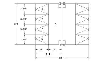
| Hinge Location / Door Area | Area Calculation | Load Calc | Load vs Rating | Pressure vs Rating | Criteria Met? |
| Top Hinge / A | (21 1/3” x 24”)/144 = 3.555 ft2 | 80 PSF x 3.555 ft2 = 284 Lbf | 284 Lbf < 300 Lbf | N/A | YES |
| Middle Upper Hinge / B | (26 2/3” x 24”)/144 = 4.444 ft2 | 80 PSF x 4.444 ft2 = 356 Lbf | 356 Lbf > 300 Lbf | N/A | NO |
| Middle Upper Hinge / B | (26 2/3” x 24”)/144 = 4.444 ft2 | 80 PSF x 4.444 ft2 = 356 Lbf | 356 Lbf > 300 Lbf | N/A | NO |
| Bottom Hinge/ C | (21 1/3” x 24”)/144 = 3.555 ft2 | 80 PSF x 3.555 ft2 = 284 Lbf | 284 Lbf < 300 Lbf | N/A | YES |
| Latches / D | N/A | N/A | N/A | 80 PSF < 85 PSF | YES |
| Result: | Opening does not meet the design pressure requirement due to hinge rating. In order to meet it, the hinges need to be replaced with higher rated ones (≥ 356 Lbf). |
Appendix C
(informative)

Door Component Impact Energy Research Project
Intertek Testing Services has completed a study on the large missile impact test specified by ASTM E1886/E1996 and its affects latches on in-swinging doors. The study was conducted to quantify the energy that would tend to shear the latch bolt in fully assembly tests and compare it to the energy delivered to the latch bolt in the ANSI A250.13 component test procedure which uses a relatively rigid fixture and a pendulum type impactor.
Background
Since ANSI A250.13 was published, tests of single point (mortise and cylindrical) latches have consistently produced failures in latches that have a history of acceptable performance when tested in full assemblies. It has been clear that much of this difference in results is due to the fact that, in assembly tests, only a fraction of the energy contained in the impactor is actually delivered to the latch and bolt.
Just before the impact event, it is known that the impacting body represents about 350 ft-lbs of kinetic energy. During the impact all this energy must be conserved. We know that some energy is accounted for by several processes:
- Energy is absorbed by the door through deformation, bending, crushing and/or tearing of the door materials.
- Energy is absorbed by deflection and movement of the assembly mass.
- Energy is absorbed and returned to the impactor (it bounces back).
- Energy is absorbed by deformation or crushing of the impactor striking surface.
- Energy is absorbed in the mounting and supporting fixture and construction.
- There are several other smaller areas of energy distribution, e.g. the sound made by the impact.
The large and obvious disparity in results between full assembly impact tests and the latch component test led to the design of an experiment that is described in this report as a means of quantifying the energy distributed to the latch bolt in a typical door assembly.
Theory
Energy, when it causes movement or deformation, is termed ‘work’. If one strikes a lump of lead with a hammer it will cause it to flatten and the ‘work’ thus done is a direct result of the energy delivered by the hammer. Thus, by creating a test arrangement that the energy is delivered through a consistent arrangement of striking surface, test body and supporting surface the deformation of the test body provides and measurement of the energy required to cause the deformation.
This deformation relationship to energy can be quantified by testing the same test body material and form in a compression testing machine. As the machine loading platen compresses and deforms the test body, the load increases. For any given point in deformation, the area under the stress/strain curve can be integrated to determine the work done on the test body and hence the equivalent amount of energy that would need to be delivered in an impact event to cause the same deformation.
Procedure
The experiment was conducted in four phases.
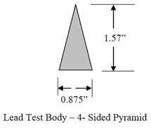
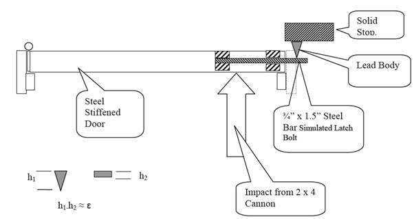
Phase I was to use a 3’-0” by 7’-0” complete door assembly with a simulated latch bolt and anvil assembly. The simulated latch bolt consisted of a 1.5” by ¾” steel bar securely attached to the door and projecting 1.25” at the normal latch location. Immediately behind the simulated latch bolt a heavy structural steel anvil was placed with a horizontal gap of 1.57”. A solid lead test body was mounted on the anvil so that when the door was struck by the impactor the energy absorbed in the latch area would result in deformation of the lead test body. The lead test body was shaped in the form of a 4 sided pyramid 1.57 inches high with a square base with each side measuring 0.875”. After each impact the height of the test body was measured and the deformation from its original height determined. The impact was delivered to the door 6 inches from the latch edge centered on the latch bolt location.
Phase II involved using the single point latch test fixture specified in ANSI A250.13 with a simulated latch bolt and anvil set up as described above for the door test and the 100 pound pendulum impactor with a 2 x 4 by 12” long wood striking surface. The level of impacts started as 350 foot pounds and was stepped down until the deformation of the lead test body was approximately equal to that observed for the door assembly test in phase I.
Phase III involved direct impact of the lead test body with the 9 pound 2 x 4 and air canon as specified in ASTM E1886/E1996 except that a 3/16 thick steel plate was affixed to the striking end of the 2 x 4 (overall weight was still 9 pounds). The pendulum impactor was also used with a 350 ft-lbf impact to compare the energy delivered between the two methods directly.
Phase IV was a series of compression tests of the lead test body using a universal testing machine in order to determine the relationship between deformation and work or energy required to produce specific levels of deformation.
Throughout these tests the deformation was determined by measuring the overall height of the pyramidal test body before and after the test. The deformed height was determined from the average of four measurements made at each of the four corners of the deformed specimen.
Multiple trials where conducted where deemed necessary and it was found that the results where repeatable to within 3-5% for all conditions of the tests.
Results
Chart 1 shows the relationship between test deformation of the lead test body used and the load applied. Integration of the area under this curve for a given deformation provides the value for ‘work’ required to produce the deformation observed.
Chart 1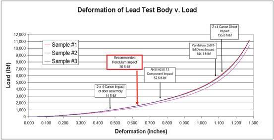
Chart 2 shows the relationship between the deformation and work for the specific test body used. The relationship is approximated mathematically as:
Work = 120 x D3 (ft-lbf)
Where: D is the deformation in the test body in inches.
The R2 correlation coefficient is 0.99.
Chart 2
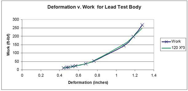
Table 1 shows the results of phase I through III of this experiment.
Table 1
| Test Condition | Impactor | Number of Trials | Average Deformation (inches) | Average Impact Energy (ft-lbf) | Work Done on Test Body (ft-lbf) |
| 20 Gauge Steel Stiffened Door | 9# 2×4@ 50ft/s | 3 | 0.475 | 354 | 14.0 |
| Pendulum Direct to test body | 100# w/12″ 2×4 | 5 | 1.083 | 350 | 144.1 |
| 2 x 4 Cannon Direct to tesr body | 9# 2x4x@ 50ft/s | 5 | 1.181 | 355.8 | 195.8 |
| Pendulum w/ A250.13 Fixture | 100# w/12″ 2 x 4 | 1 | 0.765 | 350 | 52.6 |
| Pendulum w/ A250.13 Fixture | 100# w/12″ 2 x 4 | 1 | 0.677 | 150 | 37.2 |
| Pendulum w/ A250.13 Fixture | 100# w/12″ 2 x 4 | 1 | 0.570 | 100 | 23.1 |
| Pendulum w/ A250.13 Fixture | 100# w/12″ 2 x 4 | 2 | 0.535 | 75 | 19.4 |
| Pendulum w/ A250.13 Fixture | 100# w/12″ 2 x 4 | 10 | 0.491 | 60 | 15.4 |
| Pendulum w/ A250.13 Fixture | 100# w/12″ 2 x 4 | 2 | 0.440 | 50 | 11.4 |
Analysis
The results indicate that a surprising small amount of energy from the 350 foot-pound impact of the 9 pound 2 x 4 is actually delivered to the latch in a full size door assembly test. Only about 14 foot-pounds or 4% of the available energy needs to be withstood by a typical latch bolt. In the case of the ANSI A250.13 fixture and pendulum impact at 350 ft-lbf, the energy delivered to the latch bolt is over 52 ft-lbf – about 15% of the available energy and 3.7 times the energy delivered by the 2 x 4 impact in the full test assembly.
This confirms the observation that the small scale A250.13 test of latches is much more severe than the assembly test with the 2 x 4 cannon.
Phase II indicates that, in the small scale test, a pendulum impact energy of 60 ft-lbf results in approximately equivalent shearing energy delivery to that of the full scale assembly test method.
It was observed that in the direct impact tests conducted in Phase III, the 2 x 4 cannon procedure produced 51 ft-lbs (196 vs. 144 ft-lbf) or 35% greater work on the test body than the pendulum. This is most likely due to the difference in velocity and the duration of the actual impact event. The 2 x 4 moves at a velocity of 50 ft/sec up to the point of impact whereas the pendulum velocity at impact is 15 ft/sec. This means that the 2 x 4 canon event takes place in about 4 milliseconds while the pendulum impact event takes about 12 milliseconds or 3 times as long.
If the support structure where perfectly rigid (i.e. would not move or deflect at all) this difference would not affect the energy transfer. However, in the real world, the supporting structure is not perfectly rigid and therefore it absorbs some of the energy delivered to it through movement and deflection. However, since the support is relatively massive and is subject to inertia, the time involved in the impact event has a significant influence on the outcome. Therefore the relatively shorter duration of the higher speed 2 x 4 impact allows less time for the support structure to absorb energy and hence a greater proportion of the energy delivered ends up doing work on the test body.
An example of this effect can be seen at the target range. A high speed rifle bullet will penetrate a ¼” thick suspended steel plate without noticeably moving it, but a 20 gauge shotgun slug, with equivalent energy, but traveling much slower will not penetrate but will cause a violent deflection of the same target.
Recommendations
This study has demonstrated that the small scale test specified in ANSI A250.13 for latches is indeed much more severe than the exposure provided in door assembly tests conducted per ASTM E1886/E1996 and similar wind borne debris impact tests. The level of energy transmitted to the lockset should be reduced to a value closer to 15 ft-lbs.
Use of the small scare test fixture remains viable and a simple adjustment to the pendulum energy used in the test is all that would be required to better simulate the full scale test.
Since the size, materials and stiffness of doors is variable, it is recommended that the energy level used in the small scale test be approximately twice that determined from this study. A pendulum energy of 125 ft-lbf (vertical drop height of 15”) would provide approximately 30 ft-lbf to the latch bolt and would therefore be appropriate.
A nearly identical test is specified in ANSI A250.13 for leaf hinges and these results should apply equally to the hinge component test.
Tests Conducted By: Jim Turgeson, Russ Burt, Emily Tucker
Reported By: Rick Curkeet, PE
Appendix I
Experimental Design
ANSI A250.13 Latch Impact Test Energy Transfer Experiment
Problem: The simulated latch impact test using a rigid fixture and pendulum impactor should deliver the same force and energy into the latch as occurs in an assembly when the door is impacted by the 2 x 4 missile.
Experiment:
Principle: A given amount of energy delivered by a single impact will cause a specific amount of deformation in a solid lead body such as a cylinder, pyramid or cone. Similar deformation resulting from different methods of delivering the impact indicate similar energy transfer.
First phase is to run a series of tests using a door and the set-up as shown above to establish the effect of the standard test energy as transmitted to the test body.
Phase II – Once the level of deformation produced is established, the same test body will be used in the latch impact fixture and the level of impact energy will be increased in increments until the deformation of the test body equals that established in the first phase of the experiment. Ten replicates will be performed at this level to establish the degree of repeatability.
Phase III will be direct impact of the test body with the 9 pound 2 x 4 at 50 feet per second and with the 100 pound pendulum with the 3.5 foot drop height to evaluate the relative direct energy transfer.
Phase IV will be to compression test the lead test body in a universal testing machine to determine the work (or energy) required to produce a specific level of deformation.
The test bodies will be solid lead pyramids that produce a deformation of 25 to 75% of the initial height at impacts within the range being studied.