Accelerated Physical Endurance Test Procedure for Steel Doors
SDI 131-24
View PDF
Table of Contents
- Purpose
- Reference Documents
- Apparatus and Equipment
- Preparation for Test
- Test Specimen
- Cycle Test
- Twist Test
- Acceptance Criteria
1. Purpose
The purpose of this test procedure is to provide manufacturers with an accelerated method of testing the performance of doors. This test procedure will provide performance data for comparative purposes and is not intended to simulate field operating conditions. This test will subject the product to more severe conditions than those experienced in normal field operation.
2. Reference Documents
- NSI/BHMA A156.7-2022, Template Hinge Dimensions
- ANSI/SDI A250.4-2022, Test Procedure and Acceptance Criteria for – Physical Endurance for Steel Doors, Frames and Frame Anchors
3. Apparatus and Equipment
The testing structure shall be constructed as shown in Figures 1 and 2. The structure shall conform to the parts shown, except the opening width and height are permitted to vary, allowing the testing of various door sizes.
The cycling mechanism shall be positioned so that the connecting arm is perpendicular to the stop face of the door. It shall have a threaded swivel connector that is attached to the door through the lock preparation or by means of a bracket mounted directly to the door face at the vertical and horizontal location of the lock preparation.
The cycling mechanism shall have an operating stroke so that the door lock edge will be opened not less than 4 inches from the frame stop and then returned to the closed position. The minimum cycle rate shall be one cycle per second. A mechanical or electronic counter shall be used to record the cycles.
4. Preparation for Test
The door shall be hung in the frame on hinges conforming to the most current edition of ANSI/BHMA A156.7-2009, “Template Hinge Dimensions”. The hinges and their locations shall be noted on Form 1 of the report.
Care shall be taken to ensure the hinges are properly applied to the door and frame, and any required hinge fillers are in place. The initial clearances between the door and frame shall be recorded as part of the performance test report. Silencers, weather strip or gasketing shall be installed on the frame, and the stop face of the door shall contact them.
5. Test Specimen
The test shall be performed on a 3’0″ wide x 7’0″ high nominal size door; although, other sizes are permitted to be evaluated at the discretion of the sponsor.
A detailed description of the door construction shall be recorded as part of the test report. This information shall cover all components as well as applicable processes (such as welding, bonding, etc.) used for attaching and connecting components.
6. Cycle Test
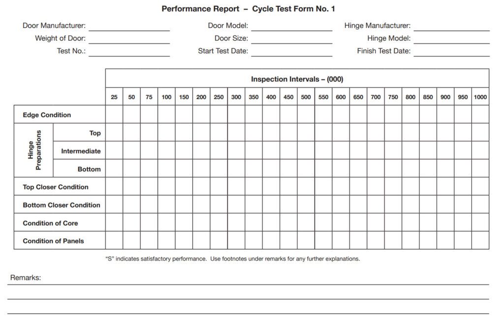
The duration of the test shall be 250,000 cycles for Level C; 500,000 cycles for Level B; 1,000,000 cycles for Level A; or longer, if specified by the test sponsor. A general inspection of the door shall be made at 25,000 cycle intervals for the first 100,000 cycles and at 50,000 cycles thereafter until the completion of the required number of cycles. The general inspection shall cover all components readily accessible, such as face skins, exposed hinge and/or lock edges, head and sill closures, flush-closing channels, hinge reinforcements, etc. Additionally, the inspection shall cover the welding, bonding, staking, mechanical interlocking, etc., used to connect the various door components.
The results shall be recorded on a standard performance report “Cycle Test Form 1” found below.
Figure 1 – Cycle Test Detail
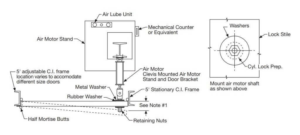
NOTES:
- Door should open approximately 4″
- Cycle Rate – minimum one cycle per second
- Door to contact mute
When an independent individual or organization is employed to certify the overall performance of the door design, they shall validate the initial, mid-point, and final observations.
7. Twist Test
The deterioration of the door strength during the cycle test, if any, shall be checked through a series of twist tests. These tests shall be performed before the cycle test begins and at 25,000 cycle intervals for the first 100,000 cycles and at 50,000 cycle intervals for the balance of the test.
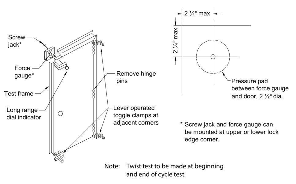
At recorded intervals, the hinge pins shall be removed and the door moved to the twist test fixture (if a separate fixture is used) and clamped in place as shown in Figure 2.
If the same fixture is used for both the cycle test and twist test, the hinge pins shall be removed and the door clamped in place as shown in ANSI/SDI A250.4.
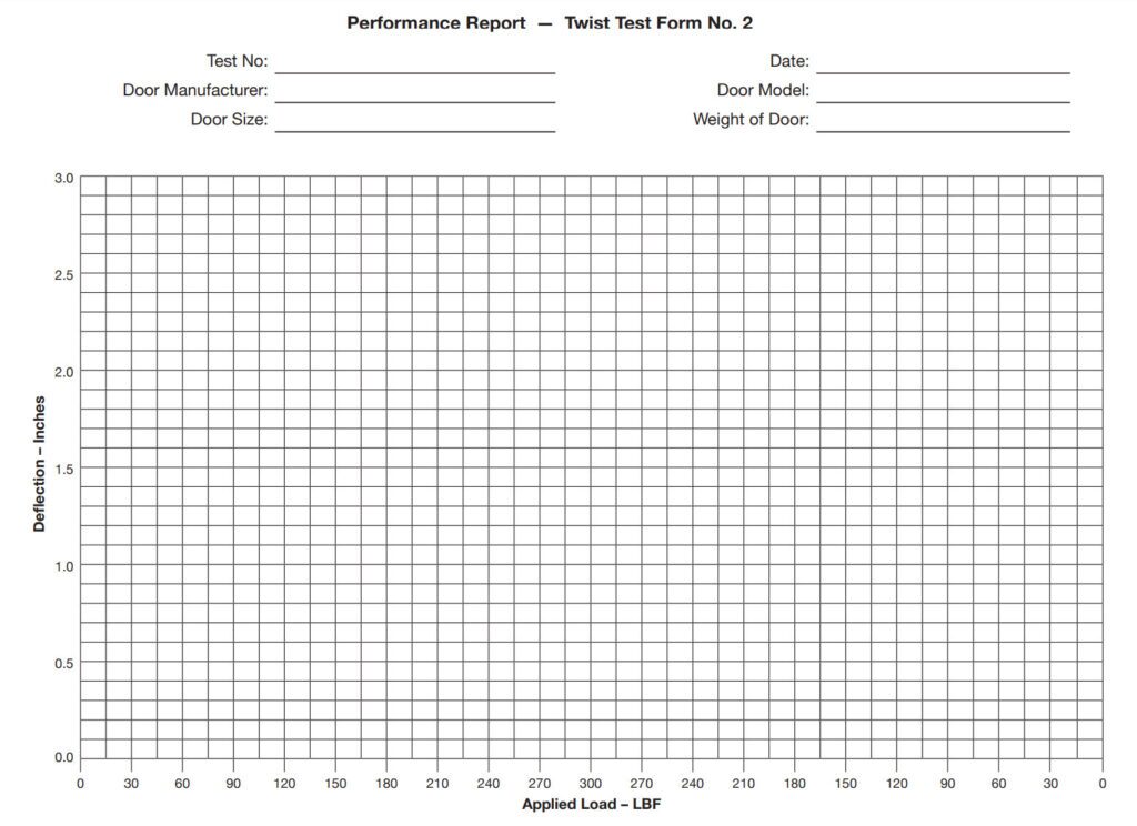
Loads in 30-pound increments shall be applied at the upper or lower lock edge corner through the screw jack and force gauge in an area as described in ANSI/SDI A250.4. The deflection noted on the dial indicator shall be plotted against the load applied to the corner. A maximum 300 pounds pressure shall be applied. The pressure shall then be reduced in 30-pound increments and the deflection recorded on the report form. A smooth curve drawn through the points shall graphically demonstrate the reaction of the door. Use “Performance Report – Door Test Form 2” below to graphically represent the deflections.
Measurements for deflections shall be taken one minute or less after the force has been stabilized.
At the completion of each twist test, and prior to the continuance of the cycle test, the hinges shall be inspected and lubricated or replaced, if necessary.
Figure 2 – Twist Test Detail
8. Acceptance Criteria
8.1 Doors shall not show any visible signs of metal fatigue cracking, or deformation on the edges or the door face.
8.2 Doors of either laminated or welded construction shall not delaminate or have weld breakage in excess of 10% of total bonded or welded surface.
8.3 Top, bottom, or edge channels must remain securely in place, with no signs of weld or bond breakage.
8.4 Doors of stile and panel or stile and rail construction shall not be misaligned.
8.5 Where visible seams are inherent in the door design, no opening or spreading shall occur.
8.6 As a result of the twist test, the maximum deflection shall not exceed 2-1/2″ when loaded to 300 lb for Level C doors. For Level B and A doors, the maximum deflection shall not exceed 1-1/4″ when loaded to 300 lb.
8.7 Permanent deflection measured within 5- minutes after the force is removed shall not exceed 1/8″.