American National Standard
Hardware Preparation in Steel Doors and Steel Frames
ANSI/SDI A250.14-2023
View PDF
Table of Contents
Figures
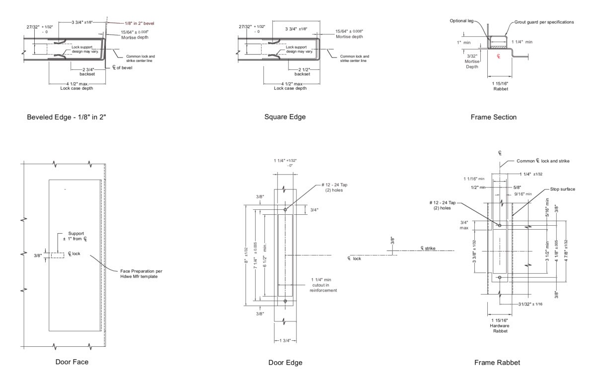
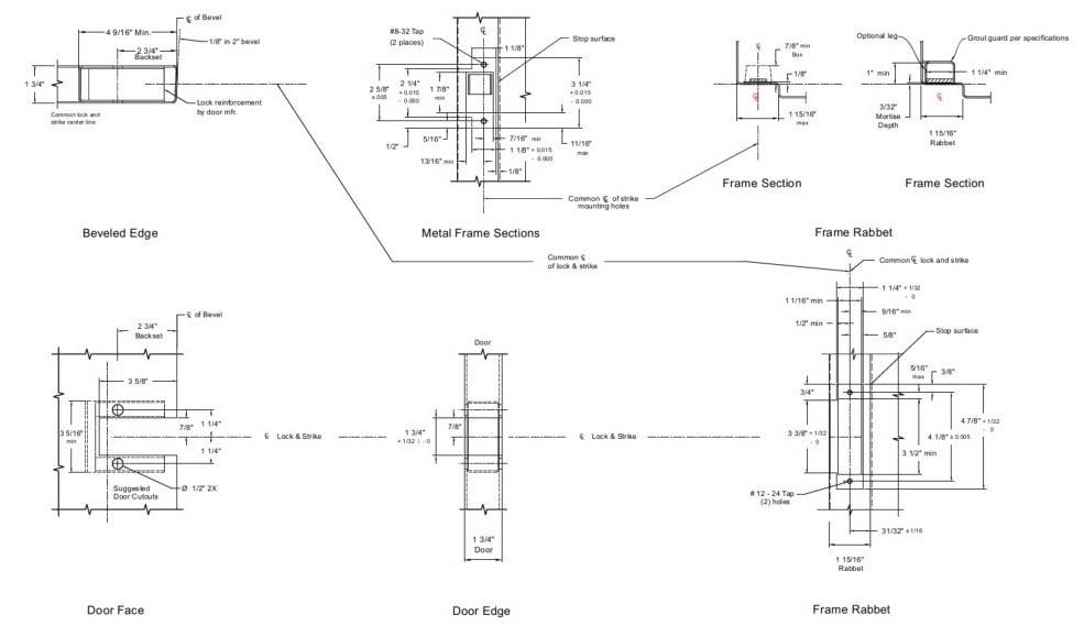
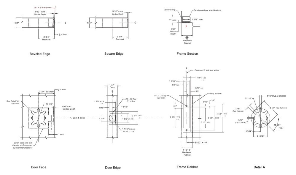
- Preparation of 1-3/4″ Steel Doors and Steel Frames for Mortise Locks
- Preparation of 1-3/4″ Steel Doors and Steel Frames for Mortise Locks with Escutcheon Trim
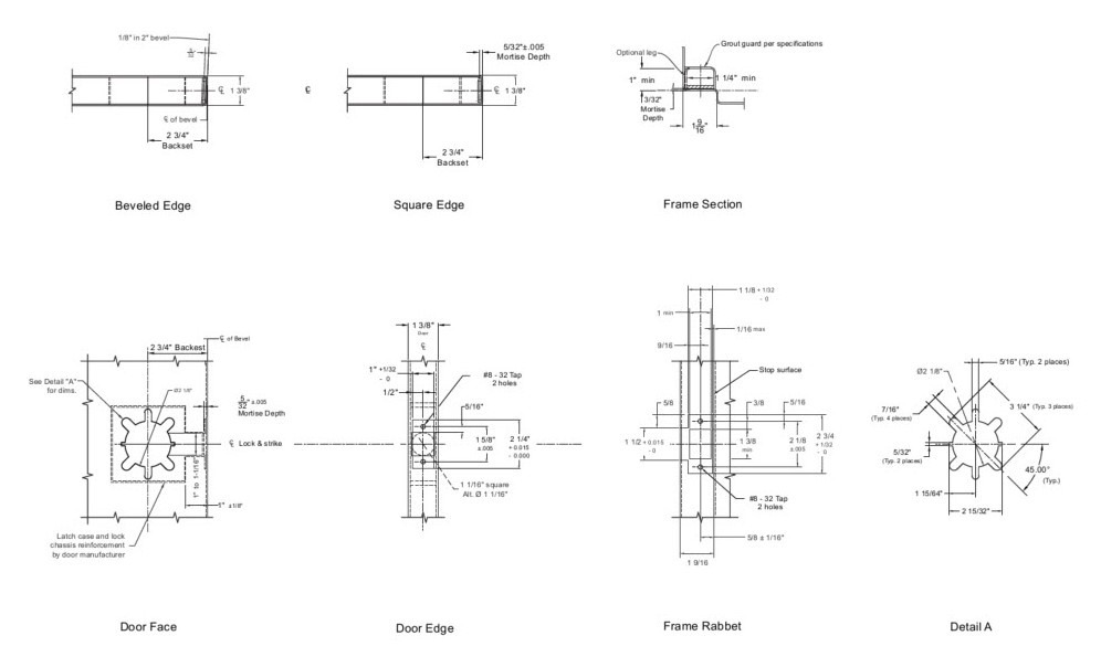
- Preparation of 1-3/8″ Steel Doors and Steel Frames for Mortise Locks
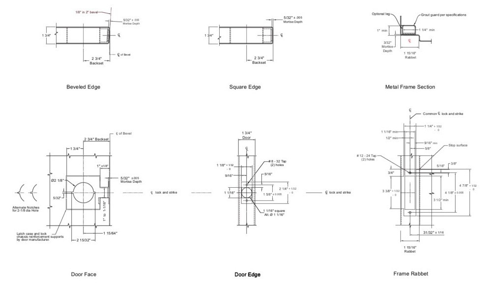
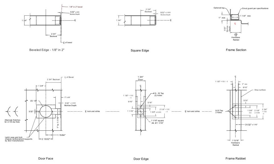
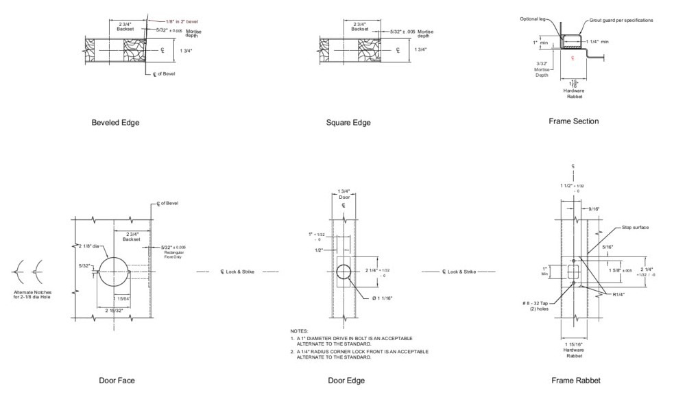
- Preparation of 1-3/4″ Steel Doors and Steel Frames for Bored Locks
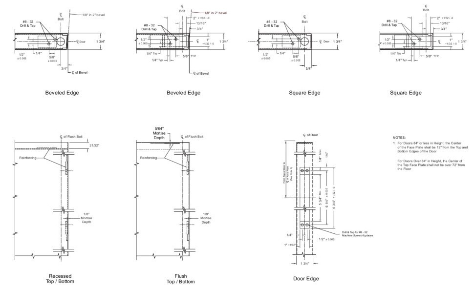
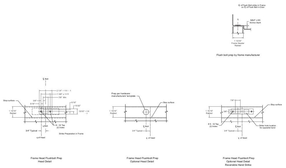
- Preparation of 1-3/4″ Steel Doors and Steel Frames for Manually Operated Lever Extension Flush Bolt
- Preparation of 1-3/4″ Steel Doors and Steel Frames for Manually Operated Lever Extension Flush Bolt Strike
- Preparation of 1-3/4″ Steel Doors and Steel Frames for Preassembled Door Locks
- Preparation of 1-3/4″ Steel Doors and Steel Frames for Bored Deadlatches
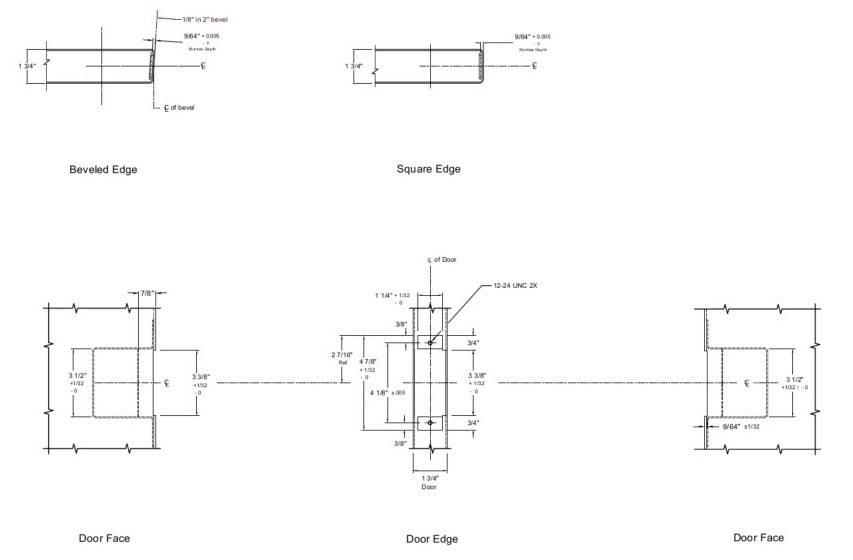
- Preparation of 1-3/4″ Steel Doors for Open Back Strikes
- Preparation of 1-3/4″ Steel Doors with Wood Edges and Steel Frames for Bored Locks
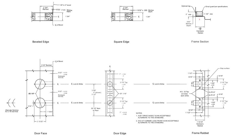
- Preparation of 1-3/4″ Steel Doors with Wood Edges and Steel Frames for Double Locks
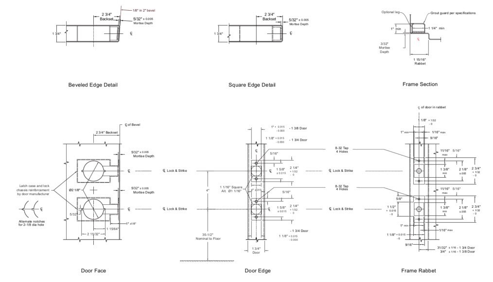
- Preparation of 1-3/4″ Steel Doors and Steel Frames for Double Locks with 4″ Centerline Spacing of Combined or Interconnected Lock or Latch
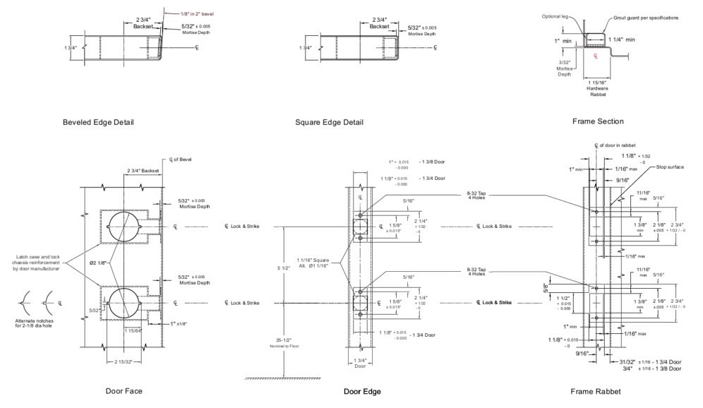
- Preparation of 1-3/4″ Steel Doors and Steel Frames for Double Locks with 5-1/2″ Centerline Spacing of Combined or Interconnected Lock or Latch
- Preparation of 1-3/8″ Steel Doors and Steel Frames for Bored Locks with Lever Handles
- Preparation of 1-3/4″ Steel Doors and Steel Frames for Bored Locks with Lever Handles
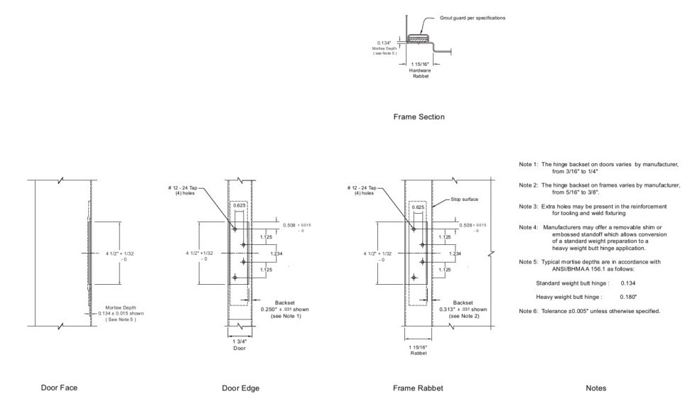
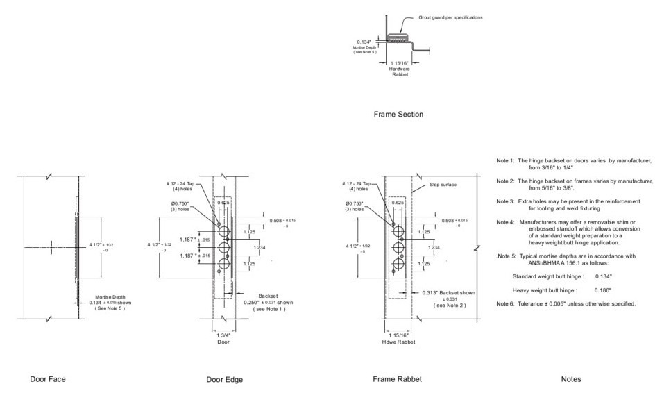
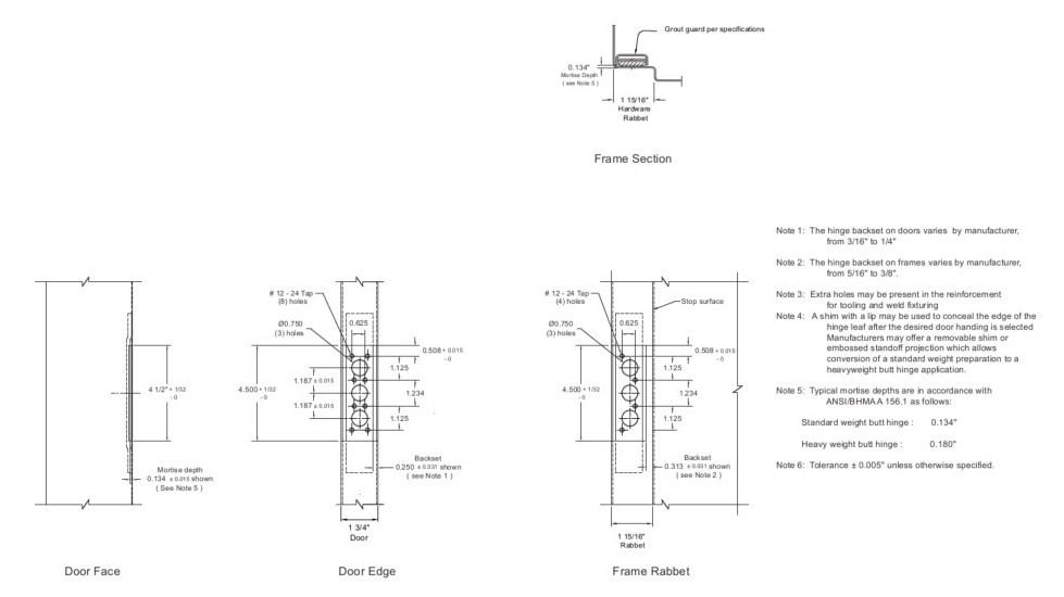
- Preparation of 1-3/4″ Handed Steel Doors and Steel Frames for 4-1/2″ Full Mortise Hinge
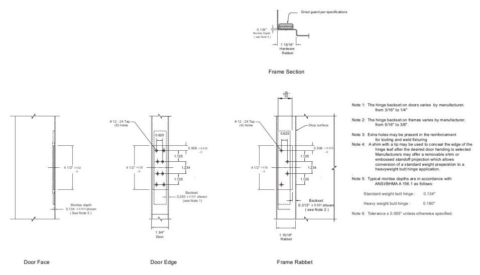
- Preparation of 1-3/4″ Non-Handed Steel Doors and Steel Frames for 4-1/2″ Full Mortise Hinge
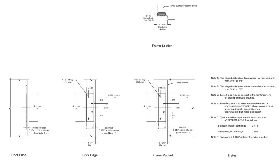
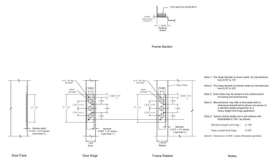
- Preparation of 1-3/4″ Handed Steel Doors and Steel Frames for 5″ Full Mortise Hinge
- Preparation of 1-3/4″ Handed Steel Doors and Steel Frames for 5″ Full Mortise Electrified Hinge
- Preparation of 1-3/4″ Handed Steel Doors and Steel Frames for 4-1/2″ Full Mortise Electrified Hinge
- Preparation of 1-3/4″ Non-Handed Steel Doors and Steel Frames for 4-1/2″ Full Mortise Electrified Hinge
1. Scope and Purpose
1.1 This standard covers all significant dimensional attributes for mounting common hardware products in steel doors and frames. All dimensions shall be as shown on the accompanying drawings.
1.2 This standard was developed to show only the most commonly used preparations for door hardware, and provide targets for standardization. Where multiple configurations are in common usage, separate drawings are provided. For other configurations, it is recognized that these standards may be used in part, or with exceptions, while still providing some degree of basic guidance and standardization.
2. General Requirements
2.1 Preparations covered by this standard are intended for use in doors 1-3/4 inches and 1-3/8 inches in thickness unless otherwise specified.
2.2 The center line of the lock in the door shall be located in reference to the center line of its strike.
2.3 Location of operable parts in accessible openings shall be between 34 and 48 inches unless otherwise specified. Consult local building codes and Authority Having Jurisdiction for exceptions.
2.4 Door Edge – Doors shall be furnished with a beveled lock edge unless otherwise specified.
2.5 Door Reinforcement – Doors shall be reinforced to support the requirements of the hardware application.
2.6 Tolerances for preparations are shown on individual drawings.
3. Definitions
3.1 Bored Locks Bored lock is used herein to designate locks having cylindrical shaped bodies which are mounted in holes bored in the door.
3.2 Dead-latch A spring-bolt latch in which the bolt is deadlocked against end pressure but may be retracted by either the knob or key.
3.3 Door Edge The vertical surfaces of a door to which hinges, locking or latching hardware is attached.
3.4 Beveled Edged A vertical door edge having a 1/8” in 2” slope from a plane perpendicular to the pull-side face of the door.
3.5 Door Face Surface of the door exposed to view when the door is closed.
3.6 Face Cut Out A piercing of the door face for hardware, lites, louvers or accessories.
3.7 Flush Bolt A locking device for the inactive leaf of a pair of doors that latches and unlatches either automatically or manually
3.8 Frame Frame is that portion of an opening which gives a finished appearance to a cutout in a wall and provides a square and plumb opening on which to hang a door.
3.9 Grout Guard A metal cover attached to a frame behind reinforcement for mortised or recessed hardware items, to prevent grout from entering the mounting holes. Also referred to as Dust Cover Guard, Masonry Guard, Mortar Guard, or Plaster Guard.
3.10 Head Horizontal frame member atop of opening or top of transom frame.
3.11 Hinge Face That face of the door viewed when observing the hinge knuckles on the door and frame.
3.12 Interconnected Lock A mechanically interconnected locking mechanism having a separate latch bolt or dead locking latch bolt and dead bolt designed for installation in round bored openings in the edge and face of a door.
3.13 Junction Box A metal cover provided to allow for the connection or termination of electrified hardware component wiring.
3.14 Lock Backset The horizontal distance from the door edge centerline measured at the door thickness, to the centerline of the lock hub or cylinder.
3.15 Lock Case The main body of a mortise lock containing the working mechanism which operates the latch bolt and deadbolt.
3.16 Lock Front A plate fastened to the edge of a door through which the bolt(s) pass.
3.17 Strike A mortised or surface mounted plate fastened to the door frame into which the bolts project.
3.18 Lock Support Component inside the door used to keep the hardware in alignment.
3.19 Mortise Lock A lock or latch fitting into a mortised cavity prepared in the edge of a door. The bolts are operated by knobs, levers, turns, thumb pieces, paddles or cylinders engaging the mortise lock or latch through holes prepared in the faces of the door.
3.20 Open Back Strike A lock strike for use on pairs of doors permitting the inactive leaf to be opened or closed independently, eliminating the need for an astragal or coordinator.
3.21 Preassembled Lock A lock fitting into a notched cutout in a door.
3.22 Reinforcement Additional door material which provides structural support for hardware.
3.23 Square Edged Doors The lock and hinge edge of the door is 90 degrees to the face of the door. Also called Universal Edged Doors.
3.24 Stop Face That side of a door viewed when observing the stop side of a frame.
4. SDI Document Disclaimers
4.1 Tolerances
All values which do not carry specific tolerances or are not marked maximum or minimum shall have the following tolerances: Linear dimensions shall be ± 1/16 inches. Weight or force shall be ± 2%. Angles shall be ± 2 degrees. Where only minus tolerances are given, the dimensions are permitted to be exceeded at the option of the manufacturers.
4.2 Gauge vs. Thickness
While the term ‘gauge’ is no longer common for defining material thickness it is still used to specify doors and frames for ordering purposes. The term ‘thickness’ is used when defining the actual dimension of an item, and the term ‘gauge’ is used in the context of specifying a particular door or frame.
4.3 Drawing
It is recommended that the individual manufacturer’s specifications be reviewed to confirm compliance with these drawings.

