Guidelines to Measure for Replacement Doors in Existing Frame Openings
SDI 135-25
View PDF
Table of Contents
- Introduction
- Preparation
- Measurements
- Frame Opening Measurements
- Frame Hardware Measurements
- Additional Measurements for Paired Opening
- Door Measurements
- Door Hardware Measurements
- Door Accessories
- Replacement Door Details
1. Introduction
This document is intended to provide guidance for measurement and recording of existing opening and/ or door dimensions required to fully detail a replacement door(s). The included figures identify the basic dimensions of frame openings and doors with standard hardware applications. Separate illustrations are provided for detailing single and paired frame openings as well as detailing individual doors.
1.1 Reference Documents
Related SDI Technical Series documents provide additional technical guidance on this topic:
- SDI-108-23 Recommended Selection and Usage Guide for Standard Steel Doors
- SDI-111 Recommended Details for Standard Steel Doors, Frames, Accessories and Related Components
- SDI-122-21 Installation Troubleshooting Guide for Standard Steel Doors and Frames
- SDI-129-24 Hinge & Strike Spacing
- SDI-134-20 Glossary of Terms for Hollow Metal Doors and Frames
1.2 Other Reference Materials
- ANSI/BHMA A156.1-2021 Butts and Hinges
- ANSI/BHMA A156.7-2022 Template Hinge Dimensions
- ANSI/BHMA A250.14-2023 Hardware Preparation in Steel Doors and Steel Frames
1.3 Notes
1.3.1 Tolerances
All values which do not carry specific tolerances or are not marked maximum or minimum shall have the following tolerances: Linear dimensions shall be ± 1/16 in. Weight or force shall be ± 2%. Angles shall be ± 2 degrees. Where only minus tolerances are given, the dimensions are permitted to be exceeded at the option of the manufacturers.
1.3.2 Gauge vs. Thickness
While the term ‘gauge’ is no longer common for defining material thickness it is still used to specify doors and frames for ordering purposes. The term ‘thickness’ is used when defining the actual dimension of an item, and the term ‘gauge’ is used in the context of specifying a particular door or frame.
2. Preparation
Installation conditions and issues will affect door operation and should be considered beforehand. Door and hardware in an improperly installed frame may function poorly. Check the floor clearance and the frame opening to verify acceptable square and level conditions. Reference SDI-122 to check for frame installation issues. Slight adjustment may be possible without removal.
Note: Frame may need to be replaced for proper function of the opening.
Basic door and frame terminology used in instructions and illustrations is explained in more detail below and in SDI-134.
The term “nominal dimensions” refers to the width and height dimensions of the frame opening. When applied to a door size, it is implicit that the door is undersized to properly fit into the nominal frame opening with proper clearances. The term “net dimension” refers to the door’s width and height dimensions. To illustrate, the door width and height dimensions in (Fig 3) are actual or “net” dimensions.
Technical Data Series SDI-129, “Hinge and Strike Spacing”, provides standard locations for hinge and strike preparations in SDI member doors and frames. Manufacturers’ locations may change so it is imperative that the hinge and strike locations be measured for replacement doors and frames.
Hardware preparations of the replacement door must be sized and located to coincide with those on the existing frame to ensure proper fit, positioning and clearances for door operation.
For hardware applications not covered below, contact the replacement door or hardware manufacturer.
3. Measurements
3.1 Tools
- Standard tape measure
- Laser tape measure
- Steel rule
- Calipers (optional)
- Framing square and small square
- Level (24″ minimum)
- Plumb bob (optional)
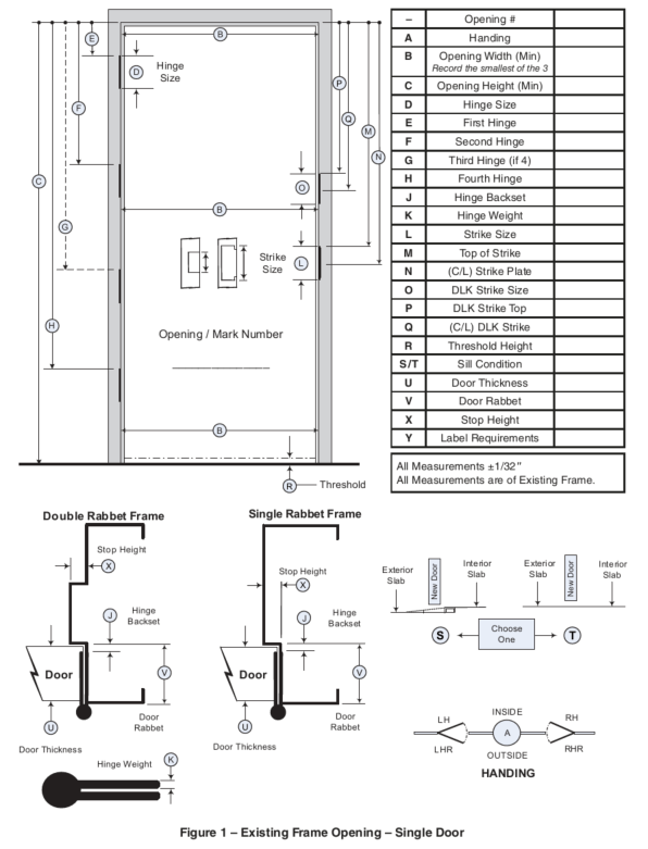
Figure 1 – Existing Frame Opening – Single Door
4. Frame Opening Measurements
4.1 The included illustrations provide guidance as follows:
- Figure 1 – frame opening dimensions for single door installation
- Figure 2 – hinge weights
- Figure 3 – frame opening dimensions for door pair installation
- Figure 4 – actual door dimensions
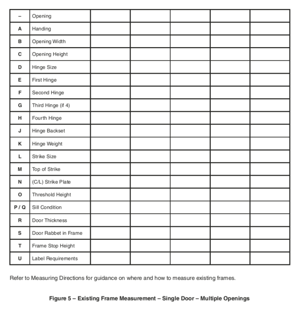
- Figure 5 – multiple frame openings worksheet
4.2 Frame opening width and height. These dimensions are to be taken from rabbet-to-rabbet surfaces. It is recommended that dimensions of both width and height be taken at three locations and the smallest of these measurements be used for sizing of the door.
4.3 Frame profile rabbet. The door thickness must be matched to this frame dimension. It is important that you have this dimension especially if you do not have the door.
Example – standard 1-3/4′′ thick door is used with 1-15/16′′ wide rabbet
4.4 Threshold height (if existing or planned) from the floor. Door undercut may need to be adjusted to allow clearance for thresholds.
4.5 Openings may have certification requirements such as fire ratings. Such requirements should be indicated by labels attached to the door (and sometimes frame). These label requirements should be noted and recorded on the form.
5. Frame Hardware Measurements
5.1 Hinge Height
The height of the hinge leaf. The most common hinge height (size) is 4-1⁄2′′, then 5′′, followed by 3-1⁄2′′, 4′′ and 6′′, then other sizes.
5.2 Hinge Weight
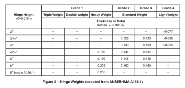
The hinge leaf thickness. Hinge mortise depth normally corresponds to this individual hinge leaf thickness. Please note that special applications exist for “doublemortise” and “surface applied”. For 4-1/2′′ hinge size, standard weight is 0.134′′ and heavy weight is 0.180′′. Standard and heavy weight vary by hinge size as shown in Figure 2, a table adapted from ANSI/BHMA A156.1. Additional hinge details are provided in A156.7 for hinge templating and A156.115 for door preps.
Figure 2 – Hinge Weights (adapted from ANSI/BHMA A156.1)
5.3 Hinge Backset
The distance from the edge of the applied hinge leaf to the frame stop. This is a critical measurement and must be accurate within 1/32′′. The most common dimension is 5/16′′. The hinge backset on the door will be properly adjusted from this measurement (typical – 1/16′′) to ensure proper clearance.
5.4 Hinge Locations
The vertical location of each hinge cutout. The recommended method of measurement is from the door rabbet surface of the existing frame head to the top of each hinge (i.e. “top-to-top”).
5.5 Strike Height
Vertical dimension of the frame strike cutout. The most common is 4-7/8′′, followed by 2-3⁄4′′ then 3-1⁄2′′.
5.6 Strike Location
The recommended measurement for replacement doors is from the door rabbet surface of the frame header to the top of the cutout (top-to-top).
6. Additional Measurements for Paired Opening
Paired openings add a variety of latching options for both active and inactive doors, particularly devices that latch vertically into strikes located in the frame head and floor/sill/threshold. If device strikes mortised into either the frame head or the floor/sill/threshold and are intended to be reused, it becomes important to note their size and centerline (C/L) of engagement. These dimensions may restrict replacement hardware options. Strike plates are indicated on the illustrations for the “Existing Frame Openings – Paired Openings” as dimensions S.1, S.2, T.1 & T.2. Consult replacement door manufacturer if moving surface-mounted strikes is necessary.
7. Door Measurements
7.1 Door Width
Dimensions taken from edge to edge across the door using steel tape. On doors with beveled edges, measurements should be taken from the wide side of the door, noting whether beveled on lock, hinge or both edges. For doors of door pairs, application or absence of an astragal affects door width.
7.2 Door Height
Dimensions taken from top to bottom edges of door using a steel tape.
7.3 Door Thickness
Dimension of door thickness using steel tape or caliper.
While the term ‘gauge’ is no longer common for defining material thickness it is still used to specify doors and frames for ordering purposes. As such, the terms ‘thickness’ is used when defining the actual dimension of an item and ‘gauge’ is used in the context of specifying a particular door or frame.
8. Door Hardware Measurements
8.1 Hinge Height
The height of the hinge leaf. The most common hinge height (size) is 4-1⁄2′′, then 5′′, followed by 3-1⁄2′′, 4′′ and 6”′′ then other sizes. Note: hinge width does not impact frame hardware measurement.
8.2 Hinge Weight
The hinge leaf thickness. Hinge mortise depth normally corresponds to this individual hinge leaf thickness where 0.134′′ is the most common (standard weight), followed by 0.180′′ (heavy-weight), then other less common thicknesses. Please note that special applications may exist for “double-mortise” and “surface applied” hinge mortises.
8.3 Hinge Backset
The distance from the edge of the applied hinge leaf to the door face nearest the frame stop. This is a critical measurement and must be accurate within 1/32′′. The most common dimension is 1/4′′.
8.4 Hinge Locations
The vertical location of each hinge cutout. The recommended method of measurement is from the top of the door to the top of each hinge (i.e., “top-to-top”).
8.5 Latch Dimension
The width and height of the latch plate on the edge of the door. The most common are cylindrical (1-1/8′′ x 2-1/4′′) and mortise (1-1/8′′ x 8′′).
8.6 Latch or Lock Location
Commonly specified from the floor (bottom of frame) to centerline (C/L) of cutout in edge of door or centerline (C/L) of strike in new installation. The recommended measurement for replacement doors is from the top of the door to the top of the cutout in edge of door if applicable or top of door to centerline (C/L) of latch actuating hole (i.e., “top-to-top”).
8.7 Lock Backset
The horizontal dimension from the door edge to the centerline (C/L) of the latch actuating hole on face of door. The most common backset dimension is 2-3/4′′ for cylindrical and mortise locks. Doors with beveled lock edges should be measured from the wider beveled side.
9. Door Accessories
Note: Instructions vary by accessory manufacturer and replacement door manufacturer.
9.1 Glass Kits / Inserts
9.1.1 Measure from top of door to top of cutout, top of outside edge of insert, or top of visible glass
9.1.2 For locating off centered inserts; measure from lock edge of door to edge of cutout; outside edge of insert; edge of visible glass
9.1.3 Exposed glass size – specifies the resulting visible glass area shown once installed.
Figures
Figure 3 – Existing Frame Opening – Door Pair
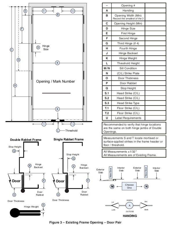
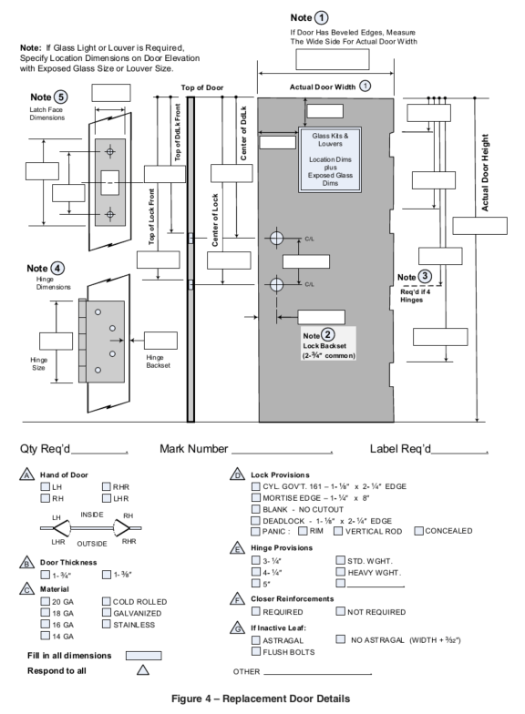
Figure 4 – Replacement Door Details
9.2 Louvers
9.2.1 Measure from top of door to either top of cutout or top of outside edge of insert
9.2.2 For locating off centered inserts, measure from lock edge of door to edge of cutout; outside edge of insert.
10. Replacement Door Details
Existing frame opening dimensions should coincide with door measurements plus proper clearances. Basic options of door construction, hardware and accessories (door gauge and finish, glass kits dimensions and location, lock provisions, closer reinforcements and astragals on pairs) are listed on Figure 4.
Figure 5 – Existing Frame Measurement – Single Door – Multiple Openings